
A reliable workflow for film lamination, OCA bonding and bubble removal starts with the product, not the equipment catalogue. Define the panel and materials first, translate quality expectations into acceptance criteria, map every process and inspection step, then choose equipment around the required working area and process method. After that, balance piece-by-piece operations against batch bubble removal, design clean material flow, confirm utilities and maintenance access, and validate the complete sequence with representative samples. This order prevents a common new-line problem: buying individually suitable machines that do not form a practical production workflow when they are connected together.
Plan in this order
1. Define the Product and Acceptance Criteria Before Selecting Equipment
The first document for a new display lamination line should describe the product envelope, not the machine specification. Record the largest assembly that must be processed, the common product families, bonding materials, film materials, expected workload and the defects that determine pass, rework or reject.
Use complete width and height rather than screen diagonal alone. A panel may also travel with a carrier, fixture or alignment tooling, so the complete loaded assembly can determine whether it fits a platform, chamber or operator workstation. For mixed production, separate products into families when they need different tooling, alignment references or process conditions.
The acceptance criteria need to exist before sample trials. Otherwise, a visually convincing machine demonstration can be mistaken for process validation even though nobody has defined the maximum alignment error, acceptable bubble condition, inspection lighting or rework rule.
Do not select from working area alone. A panel that physically fits a machine can still be a poor process fit if the alignment method, loading direction, fixture clearance, local cleanliness, operator access or downstream batch arrangement is wrong.
Once those inputs are defined, the equipment discussion becomes useful. The current equipment range for film lamination, OCA bonding and bubble removal can then be reviewed by process function, working format and application instead of treating the catalogue as the process plan.
2. Map the Complete Process Before Deciding Where Each Machine Goes
The process map should follow material from incoming inspection to final release. Include manual steps and waiting points as well as machines. A practical sequence is incoming inspection → cleaning and preparation → film or OCA alignment → lamination or vacuum bonding → bubble removal → final QC.
Confirm part identity, dimensions, surface condition and material status before the product reaches the cleanest part of the process. Damaged incoming material should not be allowed to become a later “lamination defect.”
Release only correct and usable materialPrepare the bonding surfaces with the approved method for the substrate and material system. Define where protective liners are removed and how exposed surfaces move immediately toward alignment.
Surface ready for controlled alignmentEstablish the registration datum and determine whether mechanical referencing is sufficient or whether the application needs vision-assisted correction. Inspection must use the same alignment requirement that drove the equipment decision.
Registration accepted before bondingBond the prepared layers with tooling and a process verified for the actual stack. Include loading, positioning, machine operation and unloading in the station cycle instead of counting only the active machine motion. For a closer look at how vacuum bonding helps limit trapped air, see our guide to how vacuum lamination prevents OCA bubbles.
Bonded assembly suitable for downstream processingRun a validated debubble cycle using a representative loading arrangement. Chamber size alone does not establish usable batch capacity; panel dimensions, fixture support, shelf use and product-specific process conditions also matter.
Post-lamination condition acceptedInspect the defined visual, dimensional and functional criteria, then release the part or move it into a controlled hold or rework route. Final QC should close the process record rather than operate as an isolated visual check.
Release / hold / rework decision recordedEquipment checkpoint · Film application and alignment
Choose the alignment method around the product, not the machine name
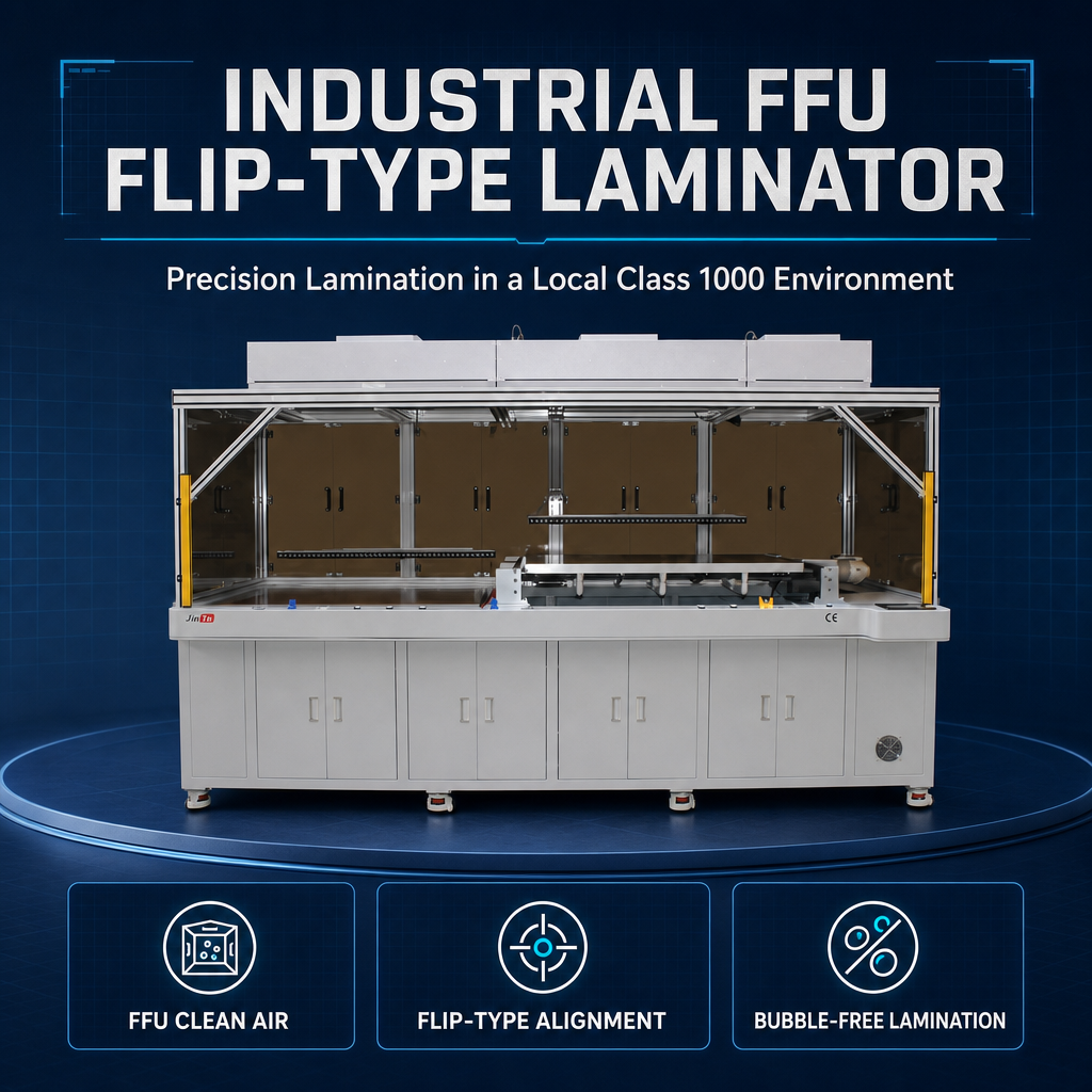
Large-format film application
700×1200 Industrial FFU Flip-Type Film Laminating Machine
This configuration is relevant when large-format G+F or F+F film application is part of the workflow and local filtered-air coverage at the bonding work zone is valuable. Its product page lists applications including OCA, polarizer, protective and functional films.
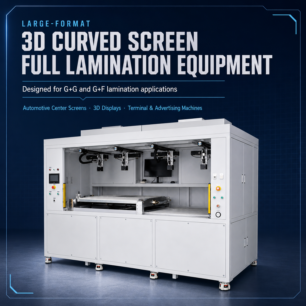
Vision-assisted alignment
600×900 CCD Film Laminating Machine
This machine is more relevant when the process needs automatic vision alignment rather than relying only on mechanical registration. The current product page identifies CCD alignment, integrated FFU units and support for multiple film and bonding combinations.
Equipment checkpoint · Vacuum bonding
Match the bonding station to the largest real assembly
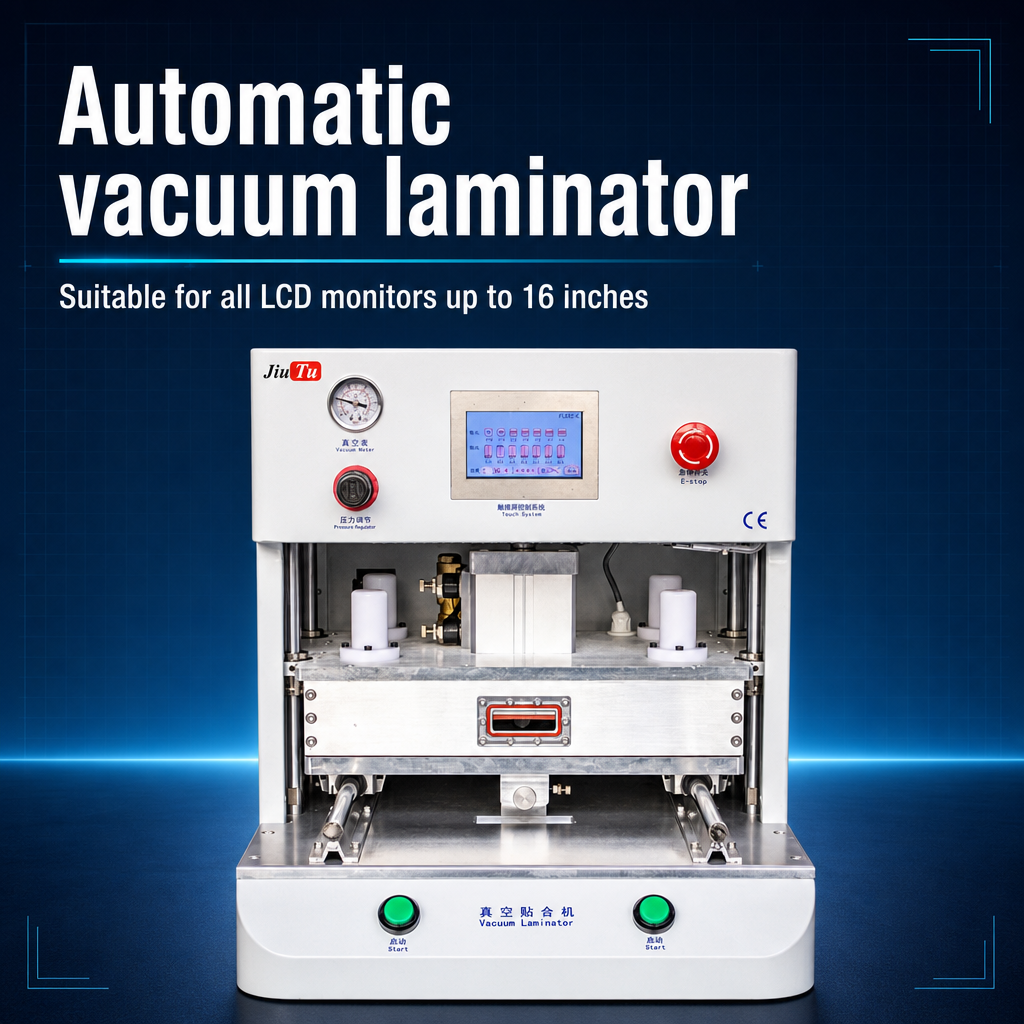
Compact vacuum bonding station
16inch Vacuum Laminating Machine
The current specification lists a maximum fitting area of 340 × 250 mm and positions this machine for OCA vacuum bonding in compact display applications. That makes it a different workflow choice from a large floor-standing laminator.
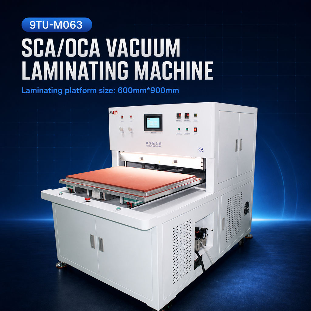
Large-format vacuum bonding
600×900 Vacuum Laminating Machine
This is a larger floor-standing bonding format for industrial display work. Its published page lists a 600 × 900 mm platform and a three-phase AC 380 V facility requirement, illustrating why utility planning and machine selection cannot be separated.
3. Separate Clean Work, General Handling, WIP and Rework in the Layout
Display lamination process planning is also contamination-control planning. After a bonding surface has been cleaned or an adhesive liner has been removed, every unnecessary movement creates another opportunity for particles, accidental contact or mix-up. The layout should therefore follow material condition rather than simply placing machines wherever floor space is available.
General zone
Incoming & Preparation
Receiving, unpacking, initial inspection, material storage and other activities that should occur before critical bonding surfaces are exposed.
Controlled core
Cleaning → Alignment → Bonding
Keep the most particle-sensitive material route short. Locate clean WIP positions so prepared parts do not return through incoming or waste-handling traffic.
Downstream zone
Debubble → QC → Release
Provide controlled batch staging, final inspection and finished-goods release without pushing completed parts back through preparation traffic.
Work-in-process also needs an assigned location and quantity rule. This is especially important when single-piece alignment and bonding feed a batch debubble stage. Parts waiting for the next batch should remain identified and protected rather than accumulating on any available bench.
Personnel movement deserves the same attention. Draw operator loading positions, material replenishment, maintenance access, inspection benches and waste removal onto the layout. A short equipment-to-equipment distance is not an efficient layout if operators repeatedly cross exposed material or block each other during loading.
Where cleanroom or clean-zone classification forms part of the project requirement, define it against the applicable standard rather than using an informal cleanliness label. ISO 14644-1 covers classification of air cleanliness by particle concentration, while ISO 14644-14:2026 addresses assessment of equipment suitability for cleanrooms and associated controlled environments with respect to airborne particles.
Layout test: follow one representative panel through the drawing. Count how many times it is picked up, turned, carried across an aisle, temporarily parked or exposed after cleaning. Those handling events often reveal more about contamination and labor risk than the equipment footprint itself.
4. Balance Piece Cycles, Batch Cycles and WIP Before Calling Anything a Bottleneck
Machine cycle times alone do not reveal where an OCA production workflow will bottleneck. Alignment, film application and vacuum bonding may operate one assembly at a time, while bubble removal usually introduces batch behavior. Inspection and cleaning add operator workload that may overlap with machine time.
Start from the required good output for the planned operating period.
Include loading, alignment, machine time, unloading and mandatory inspection.
Use actual panels, fixtures and shelf arrangements for the debubble calculation.
A buffer that continuously grows is process evidence, not extra storage.
For a single-piece station, record the complete time from the arrival of one part until that station is ready to release it and accept the next. For a batch station, record loading quantity, loading time, process time and unloading time. Changeover, planned cleaning, maintenance and expected rework should remain visible instead of assuming every scheduled minute produces good parts.
Before adding another machine, check the bottleneck in this order:
- Is time being lost to avoidable handling or long travel?
- Is one operator serving several stations at the same moment?
- Does fixture preparation delay the next cycle?
- Is a batch machine waiting too long for a full load?
- Is inspection duplicated at multiple steps without preventing downstream loss?
- After these losses are removed, does measured workload still exceed verified capacity?
The bubble-removal step deserves particular attention. A chamber dimension does not tell you how many actual assemblies can be processed in a verified load. Large modules, fixtures, shelf spacing and product-family restrictions can all change usable batch capacity. The correct question is not “How large is the chamber?” but “What loading plan can be validated for the products we actually run?”
Equipment checkpoint · Post-lamination bubble removal
Choose chamber scale from the loading plan and workload
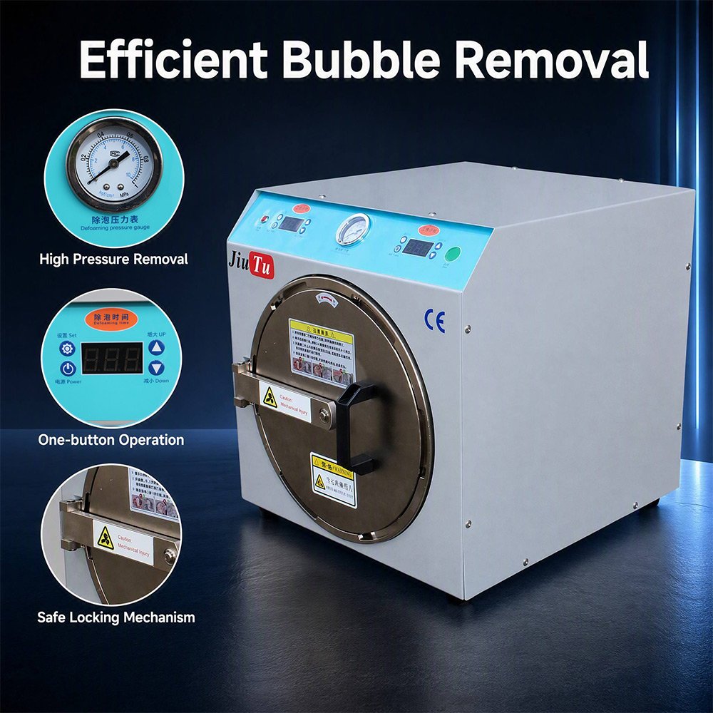
Compact workshop
260×340mm Mini OCA Bubble Remover
The product page positions this benchtop chamber for phones, small tablets and compact display assemblies. It is relevant when floor space and small-part workload matter more than large batch capacity.
View Compact Option
Repeated display processing
500×800mm Stainless Steel Defoaming Machine
Its current page identifies TFT/LCD, touch panel, industrial screen and tablet applications and emphasizes programmable process control. It is a more relevant comparison when bubble removal is a regular production step.
View Production Option
Large-module / batch workflow
1000×1600 Stainless Steel Bubble Remover
This larger chamber is more relevant when module dimensions and multi-level loading require substantial usable depth. The purchase decision should begin with the real loading plan rather than chamber size as an isolated number.
Review Large-Chamber Configuration5. Match the Equipment Combination to the Customer Type, Utilities and Process Risk
There is no single correct equipment combination for every display lamination line. A compact workshop processing phones and small panels has a different constraint set from a factory running repeated large-format assemblies. System planners should therefore define which capabilities are essential, which are useful upgrades and which would add cost without solving a verified process problem.
Profile 01
Compact workshop or repair operation
Prioritize actual maximum part size, bench space, simple material movement and a bubble remover sized for the routine workload. Large industrial platforms are unnecessary when the regular parts never need them.
Profile 02
Mixed-size processing center
Focus on adaptable tooling, controlled changeover, recipe management, protected WIP and enough working range to cover the regular product mix without oversizing every process step.
Profile 03
Repeated industrial production
Place greater weight on loading consistency, alignment method, cycle balance, traceability, service access and sample validation under representative batch conditions.
Upgrade a process only when the application gives the upgrade a job to do. CCD alignment becomes relevant when the required registration cannot be controlled adequately by the simpler method under consideration. A larger vacuum laminator becomes relevant when the complete assembly and fixture require the extra working area. A larger autoclave is justified when a verified loading plan needs the capacity—not because a larger chamber automatically creates a better process.
Facility readiness should be confirmed before the layout is frozen. Product pages for different machines on the site show why assumptions are risky: compact and large industrial equipment can require different power and air infrastructure. Confirm the exact requirements of the selected configuration rather than transferring utilities from another machine.
- Electrical supply Confirm voltage, phase, power requirement, protection and the location of the final connection point.
- Compressed air and vacuum Identify which utilities are external, which are built into the equipment and whether the facility can support simultaneous operation.
- Loading and service clearance Allow for doors, moving platforms, chamber opening, fixtures, operator positions and maintenance access—not only the machine footprint.
- Material storage and WIP Provide protected locations for incoming films, prepared assemblies, batch staging and finished product.
- Maintenance responsibility Define routine cleaning, tooling care, filters or consumables where applicable, inspection tasks and spare-part expectations.
- Training and records Separate operator training from maintenance training and decide which process conditions or inspection results must be retained.
Procurement check: ask the quotation to state the scope of each step, included tooling, required external utilities, sample-testing responsibility and what remains the factory’s process responsibility. Do not assume that several compatible machines automatically constitute a complete turnkey automatic production line.
6. Validate Material Flow, Cycle Balance and Inspection with Representative Samples
A FAT-style test or pilot-production trial should validate the workflow, not merely confirm that individual machines turn on and complete a cycle. Use representative product families, including the maximum assembly and any material or geometry considered difficult.
Record dimensions, material stack, adhesive or film identification and the acceptance criteria before the trial begins.
Measure cleaning, loading, alignment, machine operation, unloading, transport and inspection instead of recording only programmed machine time.
Use representative parts and fixtures in the bubble-removal chamber so capacity discussions are based on usable loading rather than theoretical internal volume.
Confirm where a failed part goes, who approves rework and whether the route prevents contaminated or suspect material from bypassing process controls.
Make sure the process record retains the information actually required to connect material, process condition, inspection and disposition.
Trials often expose issues that are invisible on a layout drawing. A large panel may need two-person loading. Fixture preparation may consume more time than the machine cycle. The batch station may sit idle waiting for enough upstream WIP. An inspection bench may be on the wrong side of the material route. Finding these problems before production release is part of successful process planning.
Quality-critical recipes should stay tied to the tested panel, adhesive or film, fixture and equipment combination. Parameters from another display or machine should not be treated as universal settings. For recipe development, see our guide to OCA bubble-removal pressure, temperature and cycle settings.

Inspection checkpoint
SI-VMA Automatic Focusing Video Microscope
Final QC does not have to depend only on unaided visual inspection when a process requires magnified defect review or documented measurements. The SI-VMA product page lists display modules and general incoming, in-process and surface inspection among its applications, together with image capture and measurement functions.
The final purchasing package should now contain more than equipment names. It should show the process sequence, maximum product envelope, equipment scope at each step, clean-zone boundary, WIP points, rework route, expected cycle behavior, utilities, inspection method and validation responsibilities. That package gives both the equipment supplier and the factory a clear basis for configuration review.
Frequently Asked Questions
What should be defined before selecting OCA bonding equipment?
Define the maximum complete assembly, product mix, panel structure, adhesive or film material, required output, alignment requirement, accepted defects, available utilities and the required inspection method. Equipment selection becomes much more reliable after these process boundaries are documented.
How should lamination and bubble-removal capacity be balanced?
Compare the validated release rate from film application and bonding with the usable batch loading and total bubble-removal cycle. Include loading, unloading, product changes and waiting. The objective is controlled WIP and sustainable flow, not identical nominal speed numbers.
Where should inspection be placed in the workflow?
Use incoming inspection before critical processing, add an in-process check where an error would become difficult or expensive to correct after bonding, and perform final QC after the required downstream process is complete. Additional inspections should have a defined quality purpose rather than simply adding another handling step.
How can dust and rework be isolated from clean steps?
Keep unpacking, waste and general handling outside the most contamination-sensitive route, provide protected WIP locations and place suspect assemblies in a separate quarantine or rework lane. A failed part should only re-enter the process at an approved step after its disposition is clear.
Process Planning → Equipment Configuration
Build the Equipment Combination Around the Verified Product and FlowThe right equipment combination for film lamination, OCA bonding and bubble removal starts with the largest part, the actual material stack, the defect criteria and the required production rhythm. The equipment should then be configured around that process map—not the other way around.
Before requesting a configuration, prepare the information that determines working area, alignment method, bubble-removal loading, utilities and validation scope:
- Maximum panel or sample dimensions
- LCD, OLED or other display structure
- OCA, SCA, polarizer or film material
- Expected daily or shift output
- Current defects or process requirement
- Alignment and inspection requirement
- Required voltage and available air supply
- Destination and installation constraints