
Vacuum lamination prevents OCA bubbles mainly by reducing the air around the bonding interface before the display stack fully closes. With less air present, there is less gas available to become isolated between the display, OCA layer and cover component as contact develops. Vacuum alone is not enough, however. Contact sequence, bonding pressure, tooling, panel flatness, alignment, surface cleanliness and material condition all influence whether air can still escape before the interface seals. A stable process therefore controls both the chamber environment and the way the layers physically come together.
Where Does Air Become Trapped During OCA Display Lamination?
Before bonding starts, the display, OCA layer and cover or touch component are separate surfaces. Air occupies the space between those surfaces. As the stack closes, that air needs a path toward an open edge before surrounding areas make contact and seal it inside.
This is why an OCA bubble is better understood as a contact-sequence problem than as something that simply appears after lamination. If one area of the panel touches first and another area closes from a different direction, air can become isolated between the two bond fronts. Once the surrounding adhesive interface has closed, the trapped pocket is much harder to address during the same lamination step.
The useful sequence: reduce available air before the interface closes
The bonding surfaces are still separated, so air remains between and around the layers.
Evacuating the chamber reduces the amount of gas around the still-open bonding interface.
The objective is progressive contact without creating a sealed pocket between already-bonded regions.
Real assemblies do not always close as evenly as a simplified diagram. A warped display can touch first in the center or at one edge. A fixture can support one side slightly differently from another. The cover can enter the bonding area with a small angular offset. A particle can create a local high point that keeps the surrounding adhesive from contacting normally.
Defect position therefore matters. A random isolated bubble and a bubble that repeatedly appears at the same position across multiple panels should not trigger the same response. Repeated locations are a reason to inspect tooling, alignment, local support, surface condition and the path of interface closure before changing the vacuum stage.
How Vacuum Lamination Prevents OCA Bubbles Before Interface Closure
The main purpose of the vacuum stage is preventive. Evacuation occurs while the bonding interface is still open to the chamber, so the amount of surrounding air is reduced before the layers become fully enclosed. When contact then progresses across the stack, there is less gas available to become trapped inside the adhesive interface.
This distinction is important because removing air before closure is not the same as trying to force an already isolated pocket out afterward. Once a local region has been sealed by surrounding OCA contact, simply adding more force does not necessarily recreate an escape route for the trapped gas.
A practical process therefore coordinates two different actions: first reduce air around the stack, then establish contact in a controlled way. A machine can reach its intended vacuum condition and still produce an imperfect laminate if the part is contaminated, poorly supported, misaligned or allowed to make uncontrolled contact.
For applications that require bonding under reduced air conditions, an OCA vacuum laminating machine should be evaluated by working area, vacuum method, pressure control, tooling and the actual display stack rather than by one vacuum specification alone.
Surface preparation happens before this sequence and cannot be replaced by it. Vacuum does not remove a solid particle already positioned between the layers. It cannot correct a damaged OCA surface, realign a shifted cover component or flatten a structurally distorted panel.
Material condition also needs to be treated as an input to the process. OCA films, panel constructions and cover materials can have different handling and bonding requirements. Supplier guidance and representative sample testing should define the usable process window rather than settings copied from an unrelated panel or adhesive family.
Vacuum mainly addresses gas that is present around the bonding interface while the layers are closing. It should not be treated as a universal explanation for every bubble that appears after lamination. If bubbles develop later rather than immediately, review material compatibility, storage and moisture exposure, possible substrate outgassing, adhesive condition and the approved downstream process before simply extending the vacuum cycle. For delayed or reappearing defects, see how to troubleshoot OCA bubbles that rebound after lamination.
A low chamber pressure is not a complete quality result. It confirms the chamber condition at that point in the cycle. It does not confirm that the workpiece is clean, correctly aligned, flat, properly supported or closing in the intended sequence.
Why Vacuum, Contact Sequence, Pressure, Tooling and Flatness Must Work Together
Bubble prevention is a chain of interacting conditions. Vacuum changes the amount of air around the open interface, but the mechanical parts of the process determine how that interface closes. This is why troubleshooting only one machine value can miss the real cause.
The bond front needs a controlled progression so an open path remains while the remaining air leaves.
Pressure establishes contact, but more force is not an automatic solution to contamination, warp or poor support.
The fixture controls starting position and influences how consistently the panel is presented to the press.
Bow, tilt or offset can make one region close earlier than another and alter the remaining air path.
Pressure should establish controlled contact, not compensate for every defect
Bonding pressure helps the adhesive and mating surfaces develop contact. The useful pressure condition, however, depends on the actual material stack and machine configuration. If the root cause is dust, panel bow, incorrect fixture support or misalignment, raising pressure may change the visible defect without correcting its source.
Pressure distribution also becomes increasingly important as bonding area grows. A small assembly and a wide industrial panel do not present the same mechanical problem. As the contact area becomes larger, platen movement, support geometry and the way force is distributed across the workpiece deserve more attention.
Tooling controls more than position
A fixture establishes the starting geometry of the bond. It influences edge clearance, panel seating, alignment and local support. If one corner sits high or the part can shift as the pressing mechanism approaches, the interface may start closing from a different location in each cycle.
This makes tooling one of the first checks when the same defect repeatedly appears in the same region. Inspect whether the part sits fully inside the fixture, whether a locating feature creates a local high point and whether the cover component remains square to the display before contact develops.
Flatness changes the available air path
Real display assemblies can include local bow, structural frames, backlight modules or other geometry that affects support. If the center of the assembly touches first while the edges remain separated, the air path will differ from a flat interface that closes progressively from one side.
This is why sample verification matters even after working area has been confirmed. A machine may physically accommodate a panel but still require the correct fixture and process sequence for that panel geometry. Fit is a necessary condition; it is not proof of bonding quality.
Vacuum Lamination vs Post-Lamination Autoclave Bubble Removal
Vacuum lamination and autoclave debubbling act at different stages of OCA display bonding. Treating them as interchangeable can hide where a defect is actually being created.
Lamination stage
Prevent air from being trapped
Vacuum reduces the air around the stack while the interface is still forming. Contact sequence, pressure, tooling and alignment determine how the bond closes.
After lamination
Treat suitable residual bubbles
A downstream autoclave works on an assembly that has already been bonded. It does not replace clean preparation or controlled interface formation upstream.
This separation is useful during troubleshooting. A clean and correctly aligned laminate can still require an approved post-lamination treatment when residual air remains. That does not mean the primary lamination stage should intentionally accept preventable trapped air.
Likewise, a post-lamination process cannot remove a solid particle from the interface or move a misaligned cover back into position. If a defect is created by contamination, tooling or part geometry, correcting that condition earlier in the process is more meaningful than relying on downstream pressure to make the defect less visible.
The stronger production logic is therefore sequential: prevent as much trapped air as practical during bonding, inspect the laminated part, identify the remaining defect correctly, and only then use the approved post-lamination process where it is appropriate.
Keep the process boundary clear: vacuum lamination is primarily about reducing trapped-air formation while the OCA interface closes. Autoclave pressure, temperature and hold-time optimization belong to the post-lamination debubbling stage.
Why Can Bubbles or Bubble-Like Defects Still Remain?
A visible defect after vacuum bonding does not automatically mean that the vacuum stage failed. The useful next step is to identify what physically prevented complete contact or changed the way the interface closed.
Record the defect location before changing settings. A defect that repeats in the same place across several assemblies deserves a different investigation from defects that appear randomly from panel to panel.
A solid particle keeps the bonding surfaces separated locally. The surrounding void can resemble an ordinary trapped-air bubble.
Check first: cleaning, protective-film removal, static control, handling and pre-lamination inspection.
Local bow changes the distance between surfaces and can make one area contact significantly earlier than another.
Check first: actual sample flatness, fixture support, frames, brackets and whether the part is fully seated.
Incorrect relative position changes edge conditions and can alter where the contact front enters the adhesive area.
Check first: locating features, loading method, movement before pressing and alignment immediately before bonding.
OCA behavior depends on the actual material system and on how the adhesive and substrates were stored, prepared and handled.
Check first: material identification, supplier guidance, handling history and validation on representative samples.
Use defect patterns to decide what to change
If multiple panels show a defect along the same edge, inspect edge support, alignment and the contact sequence in that region. If the defect follows a fixture position, look at the mechanical support at that point. Random spots associated with visible particles point back toward cleaning and handling rather than chamber vacuum.
When testing an adjustment, change one meaningful process factor at a time where practical and keep the inspection method consistent. Changing vacuum time, pressure, fixture setup and loading technique together may produce a better-looking sample, but it does not reveal which change solved the problem.
Production records become more useful when they capture what happened before lamination as well as the final result. Panel identification, OCA material, fixture, cleaning condition, loading orientation and defect position can reveal repeatable patterns that a simple pass/fail record cannot.
What Laminator Capabilities Matter for OCA Bubble Prevention?
Equipment selection should stay tied to the same bubble-prevention problem: the machine must fit and support the real workpiece, reduce air around the open interface, establish controlled contact and repeat the process consistently. Do not choose a laminator from the display diagonal alone. The complete assembly and any required positioning or support fixture must fit the usable bonding area.
The same principle applies to vacuum performance. A larger vacuum number by itself does not tell whether the equipment provides suitable pressure control, platen movement, tooling space or process repeatability for the target panel.
- Define the complete workpiece envelope. Record the full panel width and height together with any frame, bracket or fixture that must enter the bonding area.
- Identify the real bonding stack. Specify LCD or OLED, cover glass or touch layer, OCA material and any structural features that change support or bonding height.
- Describe the defect or process objective. State whether the problem is trapped air, uneven contact, alignment, contamination or another repeatable condition.
- Evaluate vacuum and pressure together. Ask how evacuation, pressing, decompression and process control interact rather than comparing a single headline value.
- Include tooling in the size decision. Working area should accommodate the complete assembly in its real support and alignment arrangement.
- Validate representative samples. Machine fit and process suitability should be confirmed using the actual panel family and bonding material before a configuration is finalized.
Prepare these details before comparing machines
- Maximum panel or sample dimensions
- LCD, OLED or other display structure
- OCA or other bonding material
- Flat, framed or unusual panel geometry
- Current bubble or bonding defect
- Expected daily output or batch pattern
- Required tooling or alignment method
- Current cleaning and bonding process
- Available voltage and utilities
- Destination and installation requirements
Working area is especially easy to misjudge. The number on a screen specification does not represent the complete workpiece envelope. Frames and fixtures consume usable space, and a part that technically fits by display dimensions may not fit in the way required for repeatable alignment and support.
Production pattern is another selection variable. An operation processing one product family repeatedly will place more emphasis on repeatability and stable loading. A workshop handling a changing mix of panels may care more about adaptable tooling and working-area flexibility.
The following machines are useful comparison points because they represent different working-area and application conditions. They are not presented as a ranking, and the largest machine is not automatically the better choice.
Match the machine format to the panel, fixture and process requirement
The useful question is not “Which model is biggest?” It is “Which working area, pressure arrangement and tooling envelope match the real assembly without adding unnecessary machine scale?”

When a 21-inch format fits the application
21inch Vacuum Laminating Machine
This model is a logical reference when the application involves mid-to-large display bonding but does not require a full large-format floor-standing platform. Selection should still be based on the current product-page working-area specification and the complete panel-plus-tooling envelope rather than the nominal display diagonal alone.
- Why it fits this article: it demonstrates the relationship between vacuum bonding, pressure control and actual stack geometry.
- When to investigate it: when regular assemblies fit the current specified working area and a single-station format suits the workflow.
- What to confirm: panel dimensions, frame or bracket height, fixture space, OCA material and the required bonding process.
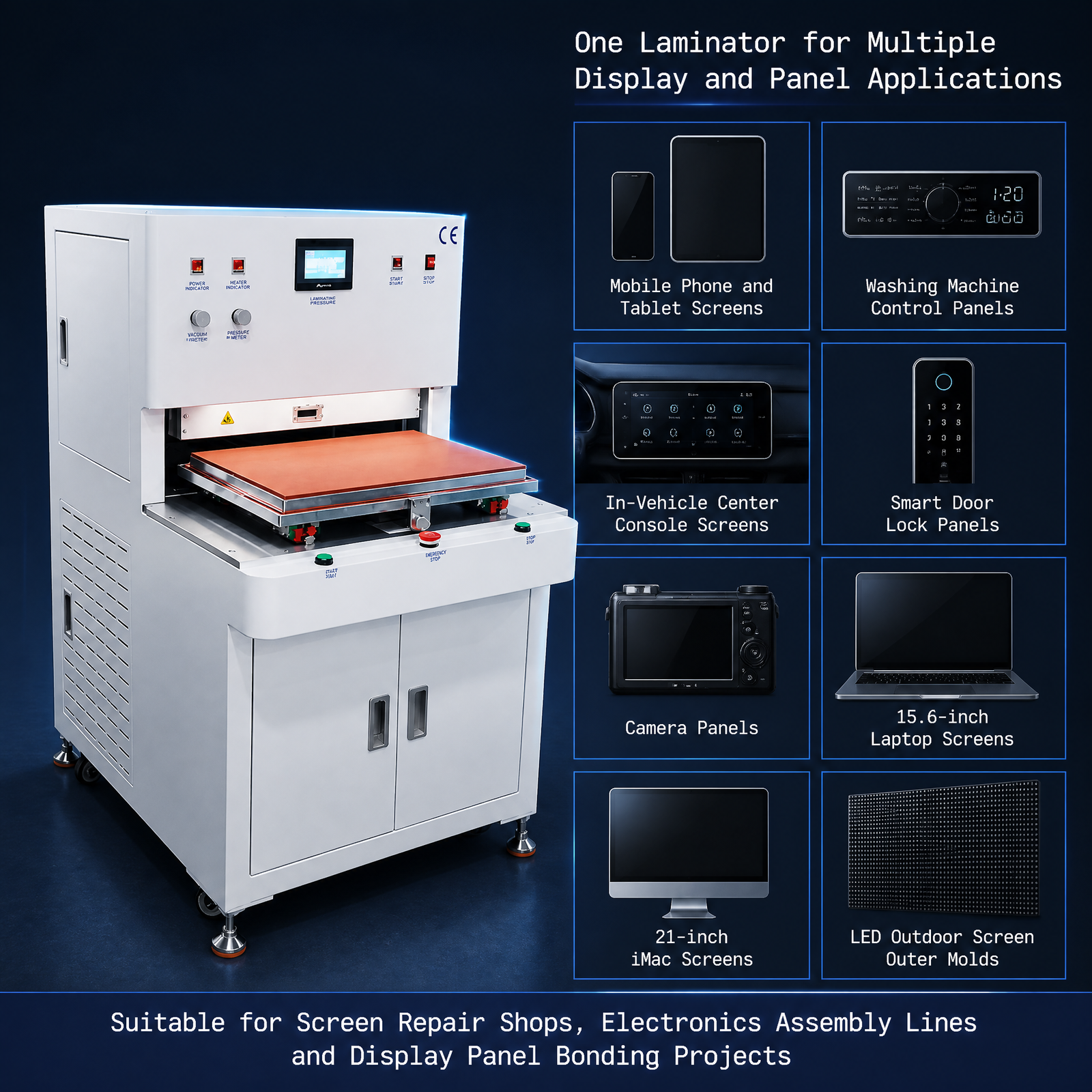
When working area and process control become more important
550×380 Vacuum Laminating Machine
The 550 × 380 mm format makes this model a more relevant comparison when assemblies and fixtures require additional working area. The selection question is whether the usable area, pressure control, platen movement and tooling space match the real bonding stack and process.
- Why it fits this article: it illustrates why vacuum should be considered together with pressure control, platen travel and fixture fit.
- When to investigate it: when mid-to-large industrial panels need more usable platform space or more structured process control.
- What to confirm: complete panel-plus-fixture dimensions, required support, adhesive system and representative sample behavior.
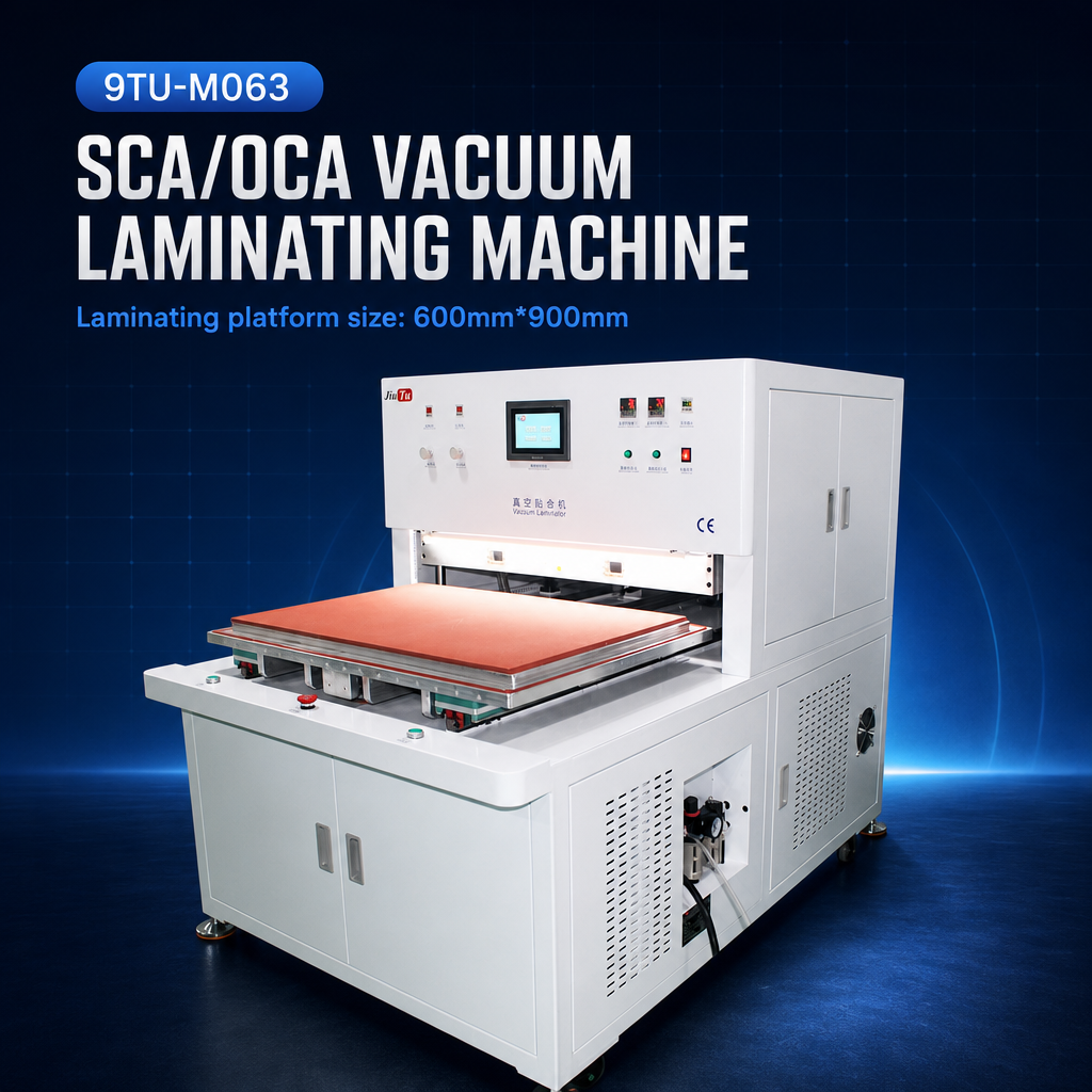
When large-format pressure distribution becomes a design issue
600×900 Vacuum Laminating Machine
A 600 × 900 mm format changes the mechanical problem as well as the machine size. It becomes relevant when wide-area pressure distribution, fixture dimensions, handling and installation requirements are part of the bonding decision.
- Why it fits this article: it shows why larger bonding area increases the importance of force distribution and consistent support.
- When to investigate it: when the real panel and fixture require a genuinely large-format bonding envelope.
- What to confirm: actual panel dimensions, pressure configuration, tooling, facility power, installation space and sample validation.
Selection rule: move to a larger or more complex laminator only when the real assembly, fixture, pressure-distribution requirement or production workflow justifies it. Extra working area by itself does not prevent bubbles if cleaning, alignment, tooling or contact sequence remain uncontrolled.
For a broader comparison, review the available vacuum laminators for LCD and OLED panels after the application requirements have been defined. The category includes several bonding-machine formats, so the logical next step is to narrow them by working area, panel structure, tooling and process requirement rather than choosing from model size alone.
Frequently Asked Questions
Does vacuum lamination eliminate every OCA bubble?
No. Vacuum reduces the air available to become trapped while the interface forms, but the result also depends on cleanliness, panel geometry, alignment, material condition, tooling and contact progression. Bubbles that appear later can also require a review of storage, moisture exposure, material compatibility or substrate outgassing. Finished samples still need inspection and process validation.
Why is an autoclave still used after vacuum lamination?
Where the approved process includes an autoclave, it serves a different stage. Vacuum lamination focuses on preventing trapped air while the bond forms. Post-lamination treatment works on suitable residual bubble conditions after the assembly has already been laminated.
How do tooling and panel flatness affect trapped air?
Tooling controls how the part is positioned and supported, while panel flatness affects the size and shape of the gap between bonding surfaces. Uneven support or bow can make one region contact earlier than another and reduce the escape path available to the remaining air.
Can the same OCA lamination process be used for every LCD and OLED panel?
No universal process should be assumed. Panel dimensions, construction, adhesive system, geometry, fixture design and production requirements can differ. Use confirmed material guidance and validate representative samples before transferring settings from another product family.
From Bubble Prevention to Equipment Selection
Control the Interface First, Then Match the Laminator to the Real Application
Understanding how vacuum lamination prevents OCA bubbles changes the equipment decision. The useful question is not simply how much vacuum a machine can produce. The machine also has to support a controlled contact sequence, appropriate pressure behavior, stable tooling, the real panel geometry and a validated material process.
Before selecting a configuration, define the assembly and the problem that needs to be controlled. That gives the equipment discussion enough context to compare working area, vacuum method, pressure control and tooling without treating any single specification as a guarantee of bonding quality.
- Panel or sample dimensions
- LCD/OLED structure
- OCA or other bonding material
- Current bubble or process problem
- Expected output
- Tooling or alignment requirement
- Required voltage
- Destination and installation conditions