
The equipment for film lamination OCA bonding and bubble removal should be selected as a process combination, not as a fixed machine package. A practical setup may include incoming inspection, surface preparation, optical film application, alignment, vacuum lamination, post-lamination bubble removal and final inspection, together with fixtures, compressed air, electrical supply and material-handling space. The correct combination depends on the display structure, adhesive or film, maximum workpiece size, required alignment, product mix, output and equipment already available. Map those conditions first; then buy the machine that controls each missing process function.
What Equipment Is Actually Needed Across the Display Bonding Process?
A useful equipment list follows the workpiece from incoming inspection to final QC. This makes it easier to see which machine solves a real process problem and which item is only conditional.
Not every project requires a separate machine for every box. A workshop may already have inspection equipment and suitable cleaning facilities. Another process may apply OCA manually but need a dedicated vacuum laminator. A larger display factory may need film application with controlled alignment, a separate vacuum bonding station and an autoclave sized around batch loading.
Do not start with “Which complete set should I buy?” Start with four questions: what operation is missing, what defect is currently uncontrolled, what is the largest complete workpiece including its fixture, and which step limits output today?
That distinction prevents over-buying. CCD alignment is useful only when registration requirements justify it. FFU clean-air control matters when exposed optical surfaces need local particle control. A larger autoclave matters when the loading plan requires the chamber volume. None of these should be included simply because another factory uses them.
After mapping the required steps, compare the current equipment for film lamination OCA bonding and bubble removal by process function, working size and workload rather than selecting a machine from one specification alone.
Incoming Inspection and Surface Preparation Come Before the Main Machines
A bonding defect is not automatically a lamination-machine problem. Dust, damaged surfaces, incorrectly prepared materials and dimensional mismatch can enter the process before the panel reaches the laminator. If those conditions are not separated from actual bonding defects, operators may spend time changing pressure, vacuum or bubble-removal settings without treating the real cause.
Look for surface damage, visible contamination, material mismatch and dimensional problems before preparation.
Identify liner removal, cleaning, turning, transfer and temporary storage points.
If yes, solve it upstream instead of asking downstream equipment to compensate for it.
Use complete width, height, thickness and fixture envelope—not only diagonal screen size.
Surface preparation should follow the requirements of the actual OCA, polarizer, cover glass and display stack. The equipment requirement may range from a controlled cleaning and inspection bench to a more structured preparation area. What matters is that cleaned parts can move into lamination without being returned through unpacking, trimming or other particle-generating activities.
This is also where material handling should be defined. Determine how a thin film is held after its liner is removed, how a large cover glass is supported, whether static or airborne contamination is an issue, and how long a prepared surface remains exposed before the next operation.
Buying tip: walk one real sample through the proposed workshop before ordering equipment. Every point where a clean surface is exposed, manually repositioned or transferred between benches is a potential requirement for better handling, inspection, tooling or local cleanliness control.
Choose Optical Film Application Equipment by Alignment and Dust-Control Needs
Optical film laminating equipment may be used for OCA film, polarizer, protective film or other functional sheets. The first selection variable is the usable working area, but size alone does not determine the correct machine.
Alignment method, film support, substrate support, product geometry, changeover frequency and cleanliness requirement can have a greater effect on day-to-day usability. A workshop processing tolerant, low-volume parts may not need the same positioning system as repeated production with registration marks and tight X/Y/rotational requirements.
Decide what level of film-application control the process actually needs
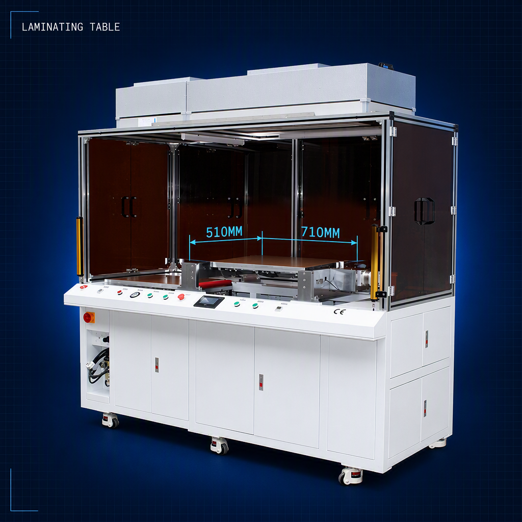
Film application · local clean-air control
510×710 Film Laminating Machine with FFU
The product is intended for film-to-substrate applications including OCA, polarizer, protective film and functional sheets. Its format is worth comparing when one workstation needs to cover multiple display sizes while keeping the bonding area under local FFU airflow.
Before choosing it, confirm the largest complete substrate, film dimensions, required positioning method, shape of the product and whether the application needs mechanical alignment or a CCD-equipped alternative.
View Product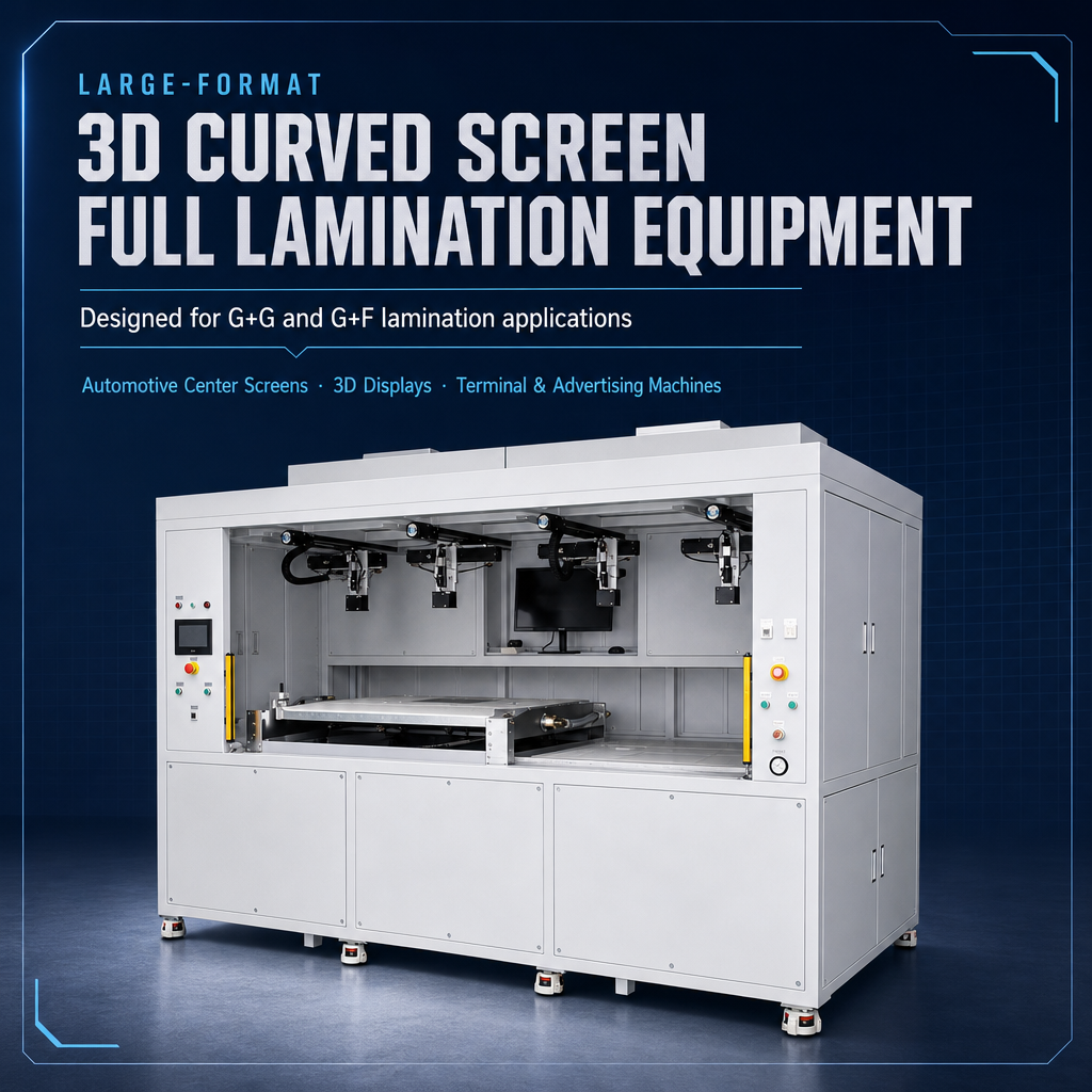
Large-format film application · CCD + FFU
600×900 CCD Film Laminating Machine
This machine combines CCD vision alignment with a large film-lamination work area and integrated FFU units. It is therefore a more relevant direction when the application includes defined alignment marks, larger touch or display panels, or product structures where manual positioning is difficult to reproduce.
CCD should still be justified by the actual drawing tolerance and material behavior. If the product can be positioned reliably by tooling, a simpler laminator may provide the required result without unnecessary complexity.
Explore CCD LaminatorOCA Alignment, Vacuum Lamination and Bubble Removal Solve Different Problems
The equipment list for LCD film bonding and bubble removal becomes easier to understand when the three central operations are separated by function. Alignment establishes position. Vacuum lamination creates the initial bond. Bubble removal treats appropriate residual air after that bond has already been made.
OCA Alignment
Positions cover glass, adhesive, touch layer or display relative to the required reference. Tooling, mechanical references or vision systems may perform this job.
Vacuum Lamination
Brings the prepared layers together under controlled vacuum, pressure and—where the validated material process requires it—temperature.
Bubble Removal
Uses a controlled pressure and temperature process to address residual air or incomplete wet-out in an otherwise correctly assembled laminate.
This separation is important because one machine cannot correct every defect created at another step. Bubble-removal equipment does not remove a solid particle trapped between layers. It cannot move a misaligned cover glass back into position. Likewise, a vacuum laminator does not replace the need for correct material preparation or final inspection.
The correct vacuum laminator is therefore chosen from the actual assembly: maximum panel and fixture envelope, flat or curved construction, adhesive system, required heating, loading method, expected product mix and output. A small or mid-size workstation and a large floor-standing laminator serve very different operating conditions even though both perform vacuum bonding.
Two vacuum-lamination directions for different workloads
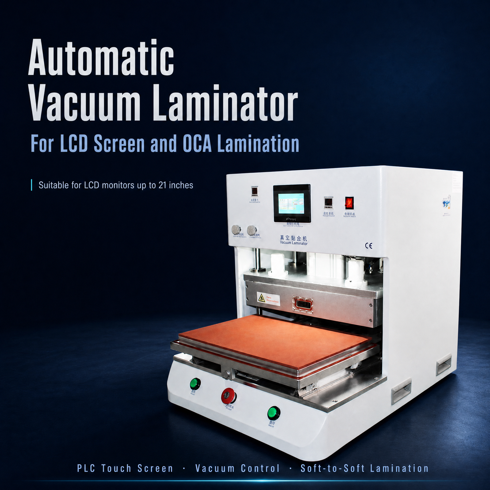
Compact industrial bonding
21inch Vacuum Laminating Machine
A practical direction for smaller industrial displays, HMI assemblies and mixed display bonding where a compact single-station laminator fits the product envelope.
Good fit when: the maximum regular assembly remains within this machine’s working range and production does not justify a large floor-standing platform.
View machine details →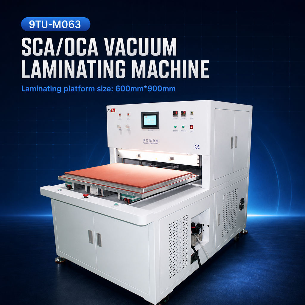
Large-format vacuum bonding
600×900 Vacuum Laminating Machine
A more relevant format for large industrial displays, digital-signage assemblies, wide-format panels and other applications where the complete panel and tooling require a substantially larger bonding platform.
Good fit when: panel size, fixture size and repeated large-format work genuinely require the additional working area and facility infrastructure.
View large-format laminator →Bubble-removal equipment should then be sized around the loading plan, not only one panel. Chamber diameter or width tells whether the largest assembly can enter; chamber depth and tray arrangement influence how many assemblies can be processed in one batch. A chamber that is physically larger than necessary can add floor-space and utility requirements without solving a real production constraint.
Exact pressure, temperature, hold time and sequence should not be copied from another product. Adhesive behavior, panel construction, geometry, loading and the original lamination result all influence the qualified process. The machine provides controllable process conditions; the working recipe must still be validated on the intended product.
Two bubble-removal formats for different operating scales
Growing workshop · floor-standing
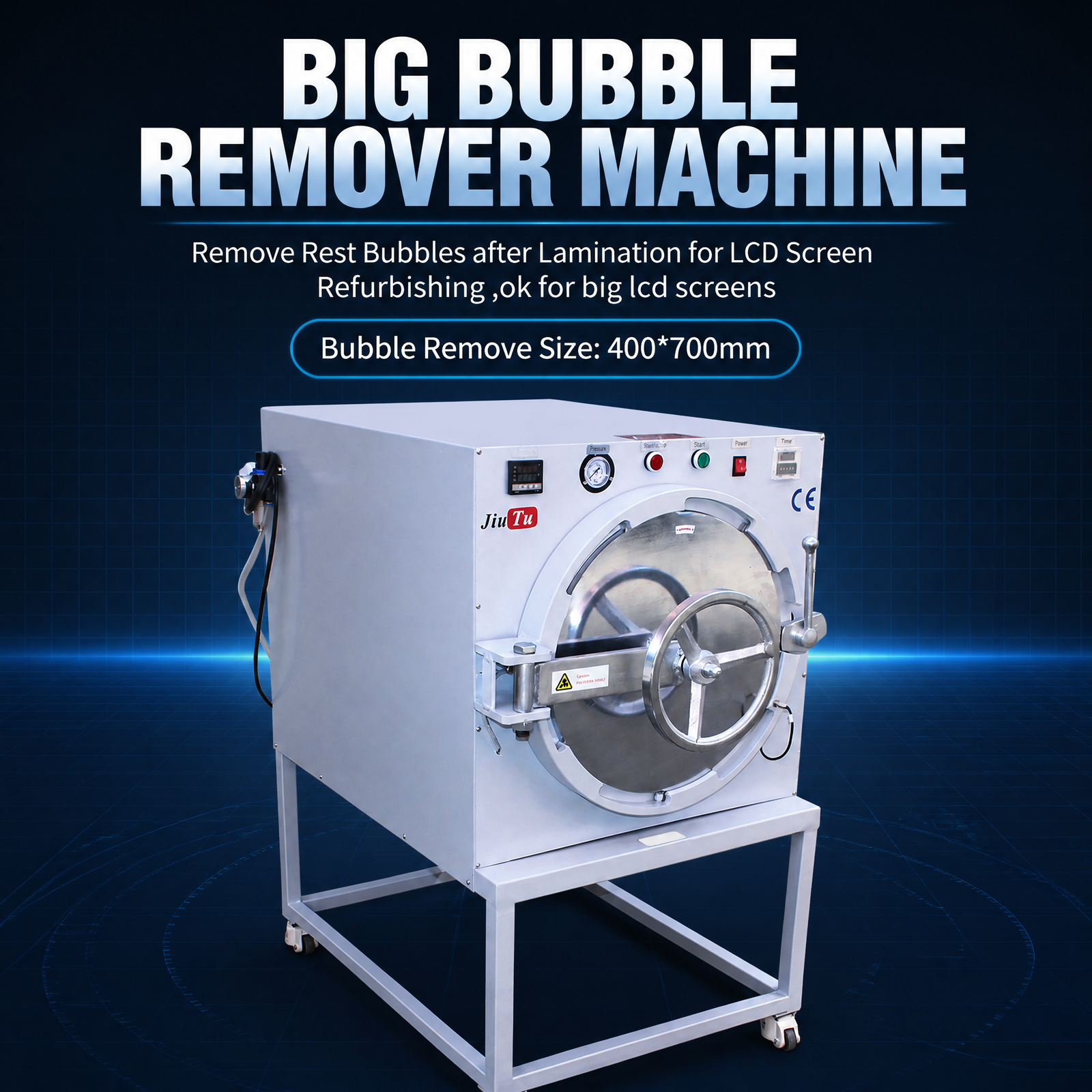
400×700 OCA Bubble Remover Machine with Mobile Stand
The floor-standing mobile format is relevant for workshops that have outgrown small benchtop bubble-removal equipment and want the chamber positioned close to different lamination or inspection stations.
Good fit when: phone, tablet or smaller display work is processed in batches and a movable floor-standing installation suits the workshop better than using bench space.
View bubble remover →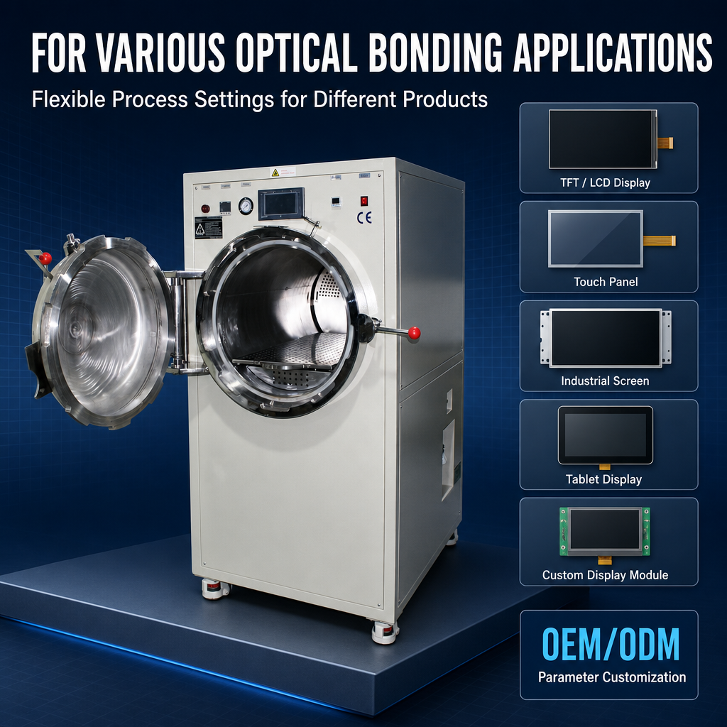
Repeated production · programmable process
500×800mm Stainless Steel Automatic Vacuum Defoaming Machine
This direction becomes more relevant where repeated optical-bonding batches require a larger loading plan and programmable control deserves more attention than minimum equipment footprint.
Good fit when: a production-oriented operation wants to validate and repeat product-specific bubble-removal cycles across regular batches.
Explore defoaming equipment →Do not select the autoclave by chamber number alone. Draw the proposed load: panel width and height, fixture, shelf spacing, quantity per layer and number of layers. The useful question is how the real workpieces occupy the chamber while allowing the validated process to operate consistently.
Final Inspection, Records, Tooling and Utilities Belong on the Purchasing List Too
The main bonding machines are only part of a usable workshop. Final inspection determines whether the process actually produced an acceptable assembly, while tooling and utilities determine whether the machine can operate as intended.
Inspection and traceability
- Define visible defects before choosing inspection equipment.
- Separate particle defects, alignment defects, bubbles and surface damage.
- Use consistent lighting and inspection timing.
- Record process conditions when troubleshooting repeated defects.
- Save defect images when location or morphology helps root-cause analysis.
Tooling and utilities
- Confirm complete panel dimensions including fixtures and carriers.
- Define dedicated versus adjustable tooling.
- Confirm site voltage before equipment configuration.
- Confirm compressed-air availability and required connections.
- Check external vacuum requirements where applicable.
- Allow loading, door-opening and maintenance clearance.
Inspection depth should follow the acceptance criteria. A well-lit visual check may be sufficient for large visible defects. Smaller contamination points, fine edge damage or dimensional questions can justify magnified imaging and measurement.
Incoming QC · process inspection · defect review
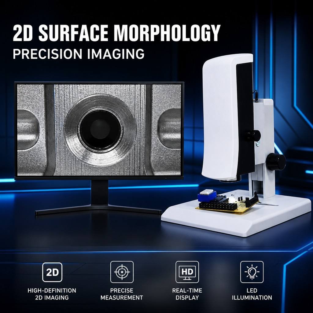
SI-VMA Automatic Focusing Video Microscope
The microscope is relevant when small particles, component details, edges or bonding defects need closer review. Its imaging and measurement functions can also support process records when a defect must be discussed between QC, production and equipment teams.
It should not be purchased simply because microscopy sounds more precise. First define the smallest defect or feature that must be detected and whether images or measurements need to be stored.
View Inspection MicroscopeA simple material-flow check before equipment is placed
This flow is intentionally not a full line design. Its purpose is to expose purchasing problems. If cleaned panels must travel back through a dusty unpacking area, the process may need better layout or handling rather than another bonding machine. If the autoclave is far from lamination and panels wait unprotected between steps, material protection and staging also become part of the equipment plan.
How Should Different Workshops Prioritize the Equipment Budget?
The same equipment list should not be applied to every operation. A useful priority system starts with the product that must be processed, the defect that must be controlled and the step that currently prevents acceptable output.
Start with the minimum functions required to make and verify a correct bond: controlled preparation, suitable film or OCA application, vacuum lamination where required, post-lamination bubble removal where required and enough inspection capability to identify the cause of defects.
Do not make CCD alignment the first investment unless alignment is already the limiting problem. Likewise, a very large autoclave provides little value if most daily work involves much smaller screens.
Priority: process completeness and usable footprint before advanced automation.
Mixed phones, tablets, laptops, industrial modules or other changing formats put more pressure on working range and tooling flexibility. Compare both the largest and smallest regular jobs rather than sizing every station from the single largest panel ever received.
Think about changeover time, fixture storage, operator access and whether separate lamination and bubble-removal stations prevent queues as workload changes. Local FFU control may also become more valuable when many product families are handled on the same workstation.
Priority: adaptable working area and tooling without buying unused capacity.
Repeat production shifts the purchasing decision toward consistency. Alignment method, programmed process control, fixtures, batch loading, inspection records and operator handoffs become more important because a small variation can be repeated across many parts.
For larger-format production, compare not only maximum size but also the actual loading method and utility requirements of each station. Where output is high enough, the lamination cycle and autoclave batch cycle should be considered together so that one step does not create an unnecessary queue.
Priority: repeatable process control and balanced capacity across the required stations.
For very large repeated loads, the site also includes larger bubble-removal formats such as the 1000×1600 Stainless Steel Bubble Remover Machine. A machine at this scale should be considered only after the panel envelope, shelf arrangement, batch loading, available floor space and process requirement have been confirmed.
Send these details before requesting an equipment configuration
A useful RFQ should allow the supplier to distinguish essential equipment from optional capability. Provide real production information rather than asking for a generic “complete OCA line.”
- Minimum and maximum panel or sample dimensions
- Complete assembly size including fixture if known
- LCD, OLED or other display structure
- Flat, curved or irregular geometry
- OCA, polarizer, protective or functional film type
- Current film and bonding process
- Existing equipment that will remain in use
- Current defects and acceptance requirements
- Required alignment method or tolerance
- Expected daily output or typical batch quantity
- Available voltage and compressed air
- Destination and installation constraints
This information gives the equipment supplier something concrete to configure. It also protects the purchaser from paying for functions that do not solve the actual process problem.
Frequently Asked Questions
Is a bubble remover required after every OCA lamination process?
No. Include bubble removal when the adhesive system, product construction and validated process require a post-lamination pressure and temperature treatment. The need should be confirmed from the material process and actual sample results rather than assumed from another workshop’s equipment list.
Can one machine combine lamination and bubble removal?
Combined formats can be suitable for compact workshops and some mixed repair applications, but evaluate the two functions separately. Confirm the true lamination working area, bubble-removal chamber capacity, controls, loading method and expected output. A single cabinet is not automatically more efficient if the two processes create different capacity requirements.
What inspection equipment is needed before and after bonding?
Match the inspection tool to the defect. Controlled visual inspection may be sufficient for obvious contamination, damage and gross misalignment. Fine particles, small edge defects, component features or dimensional questions may require a video microscope or measurement system. Define the acceptance criteria before buying the inspection instrument.
Which utilities and workshop details should be confirmed before ordering?
Confirm electrical supply, compressed air, any external vacuum requirement, equipment footprint, floor or bench location, loading clearance, chamber-door movement, maintenance access and the delivery path. Large-format equipment may have very different site requirements from compact equipment, so check the exact configuration being quoted.
How should equipment be prioritized for a limited starting budget?
Map the current process and find the first operation that is missing or uncontrolled. Fund that process function first. Add CCD alignment, FFU clean-air control, larger chamber capacity or advanced inspection only when the product, defect or output requirement justifies it. This usually creates a stronger starting process than buying the greatest number of machines possible.
Equipment Selection & Configuration Review
Choose the Equipment Combination From the Real Product and ProcessThe right equipment for film lamination OCA bonding and bubble removal is not the longest equipment list. It is the combination that controls the required preparation, alignment, bonding, bubble-removal and inspection steps for the verified material, panel dimensions, defect criteria and output.
Before comparing machines, document the current workflow, mark the main defects and bottlenecks, confirm the largest complete workpiece and identify which process functions are already available. Then compare equipment around the gap that remains.
- Panel or sample dimensions
- Display and material structure
- OCA or optical film type
- Current defect photographs
- Required alignment or QC criteria
- Expected output or batch pattern
- Voltage and available utilities
- Destination and installation conditions