
Three-dimensional composite imaging measuring instrument
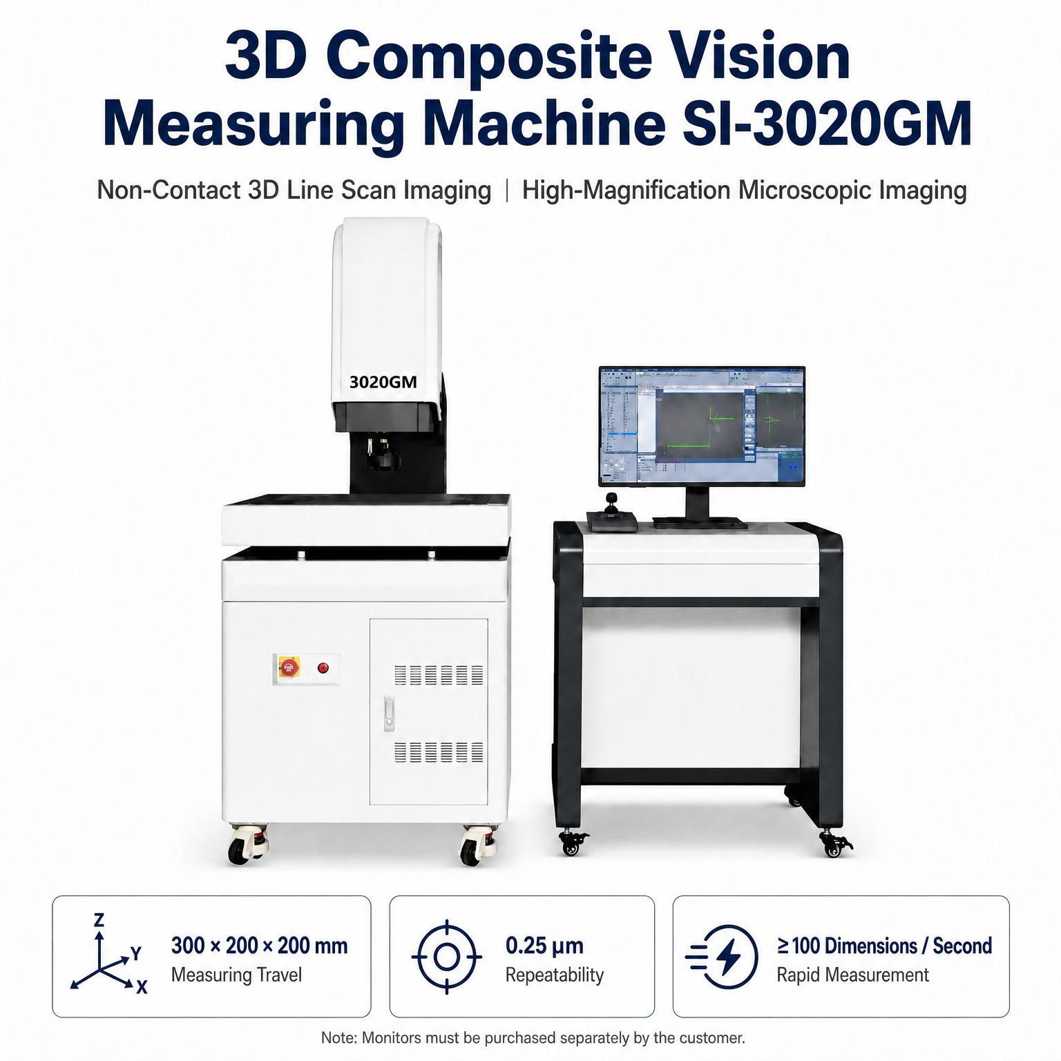
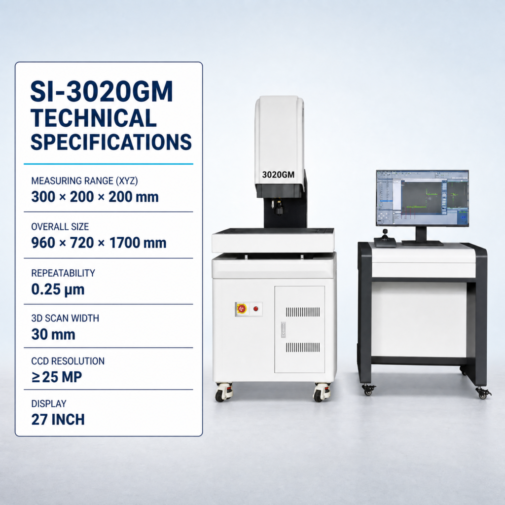
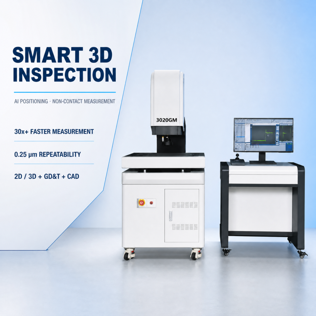
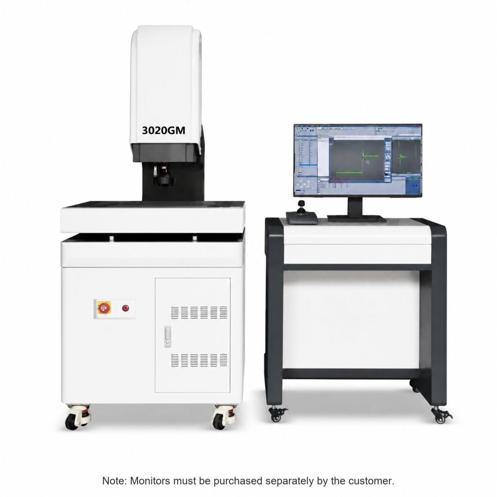
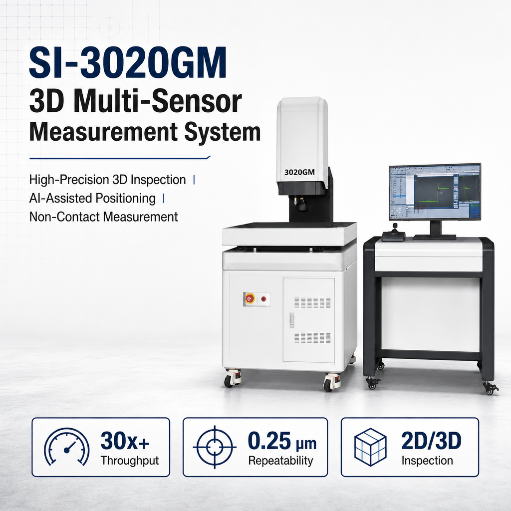
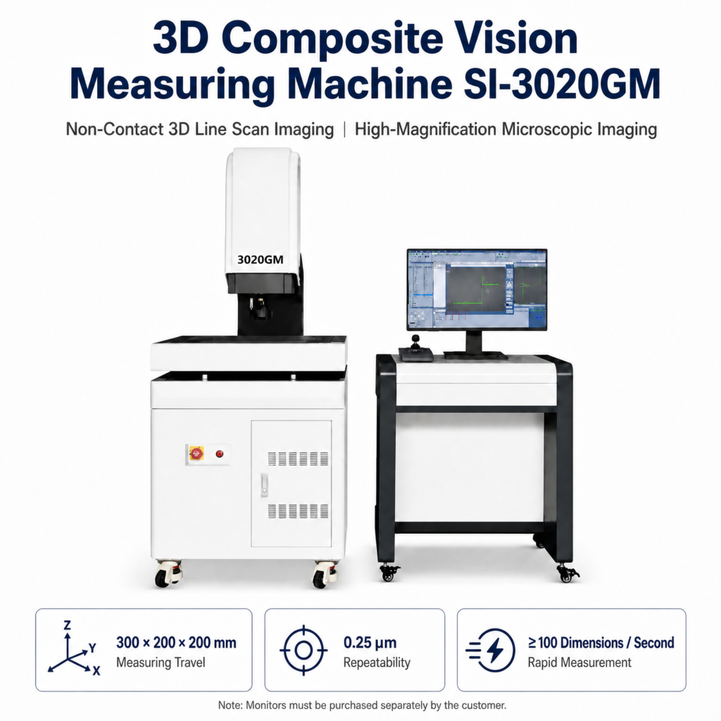
The 3020GM 3D Composite Image Measuring Instrument brings optical imaging and 3D laser scanning together on a single Grade 00 granite platform. In one automated cycle it captures 2D geometry, 3D heigh...
GET QUOTE NOW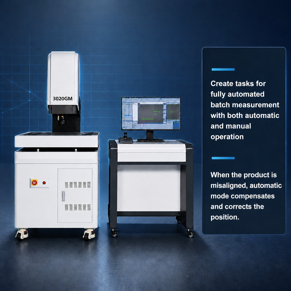
Why Engineers Choose the 3020GM
🧱 Metrology-Grade Mechanical Platform Grade 00 granite base, column and worktable on a steel frame structure 7075 aerospace aluminium worktable with automotive paint finish 95% high-transmittance optical glass stage Ground-grade, low-noise ball screws and H-grade low-noise linear guides on all three axes High-performance AC servo motors on all three axes 0.5 μm metal linear scales (3 axes) In-house four-axis motion controller and motion control system
💡 Programmable Multi-Zone Illumination Surface light: 256-level programmable five-ring, eight-zone LED cold light source Bottom light: parallel contour LED cold light source Independent control of ring and zone lets you bring out edges on reflective, matte and transparent materials without changing fixtures.
Software Capabilities Import & Output CAD drawing import and editing 3D model comparison with STP and similar 3D drawing formats Scanned contour output as point drawings — DXF, TIF and other formats Reports exported to Word, Excel, HTML and TXT
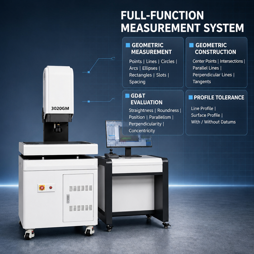
Measurable Geometry Point · line · circle (maximum, minimum and mean) · arc · spline · ellipse · rectangle · quadrilateral · slot · fillet radius · ring · spacing · distance · point cloud
Constructed Features Centre point · extreme point · endpoint · intersection · two-point line · parallel line · perpendicular line · tangent · bisector · centreline · merge · contour segmentation · radius circle · three-line inscribed circle · two-line radius inscribed circle
Geometric Tolerances Straightness · roundness · position · parallelism · perpendicularity · inclination · concentricity
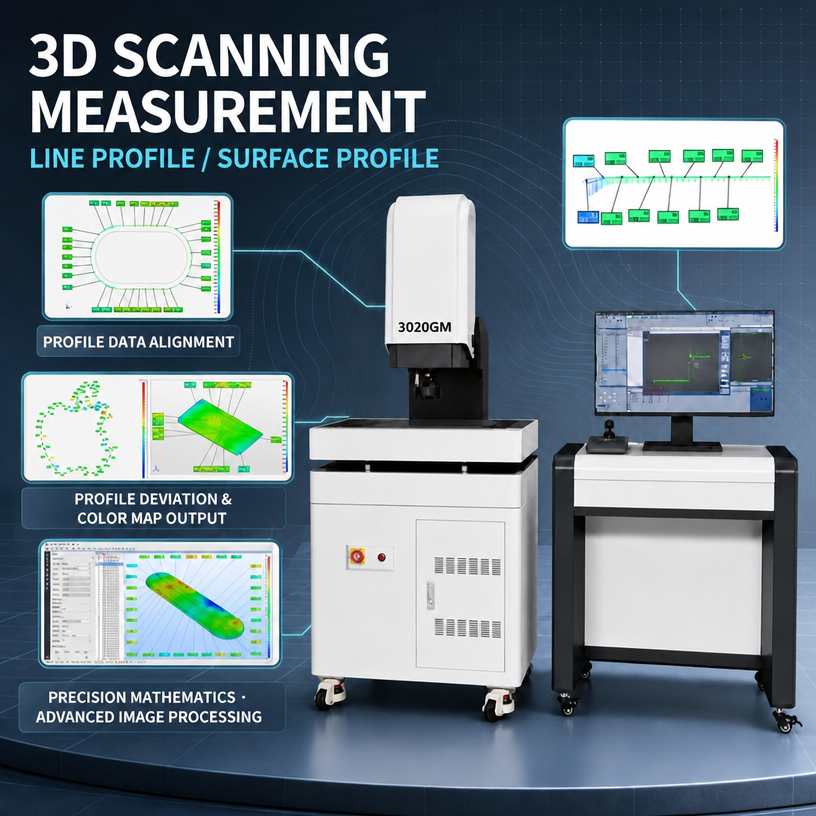
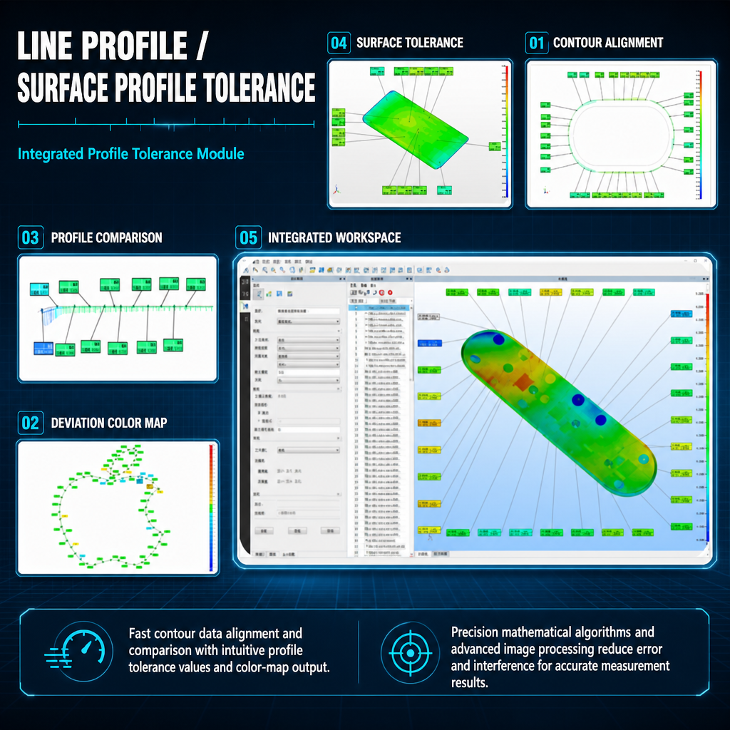
Profile Tolerance Line profile and surface profile tolerance, with or without datum reference
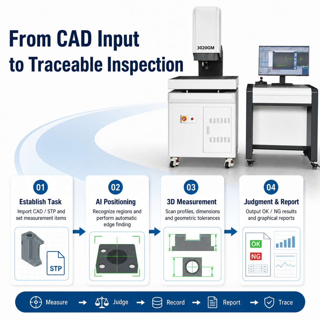
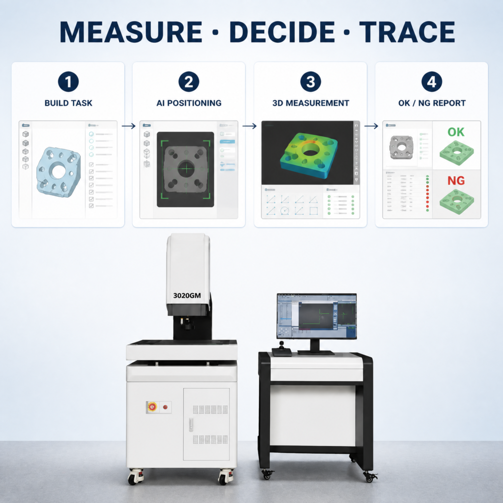
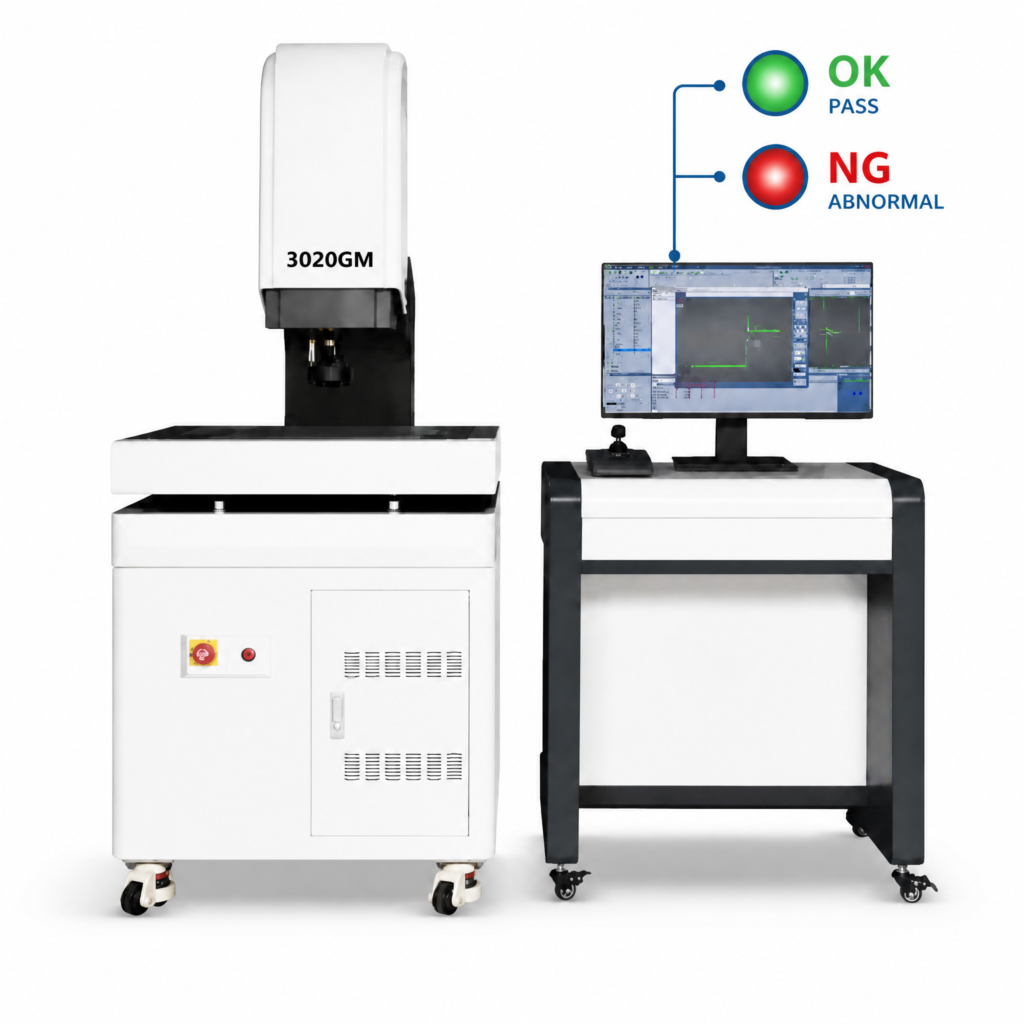
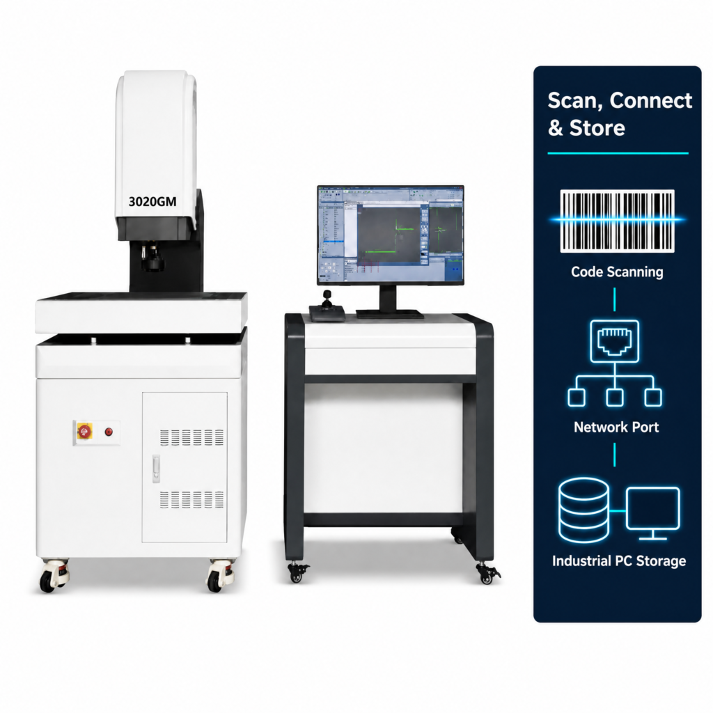
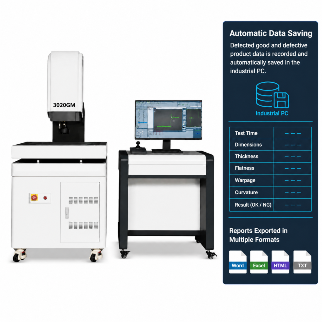
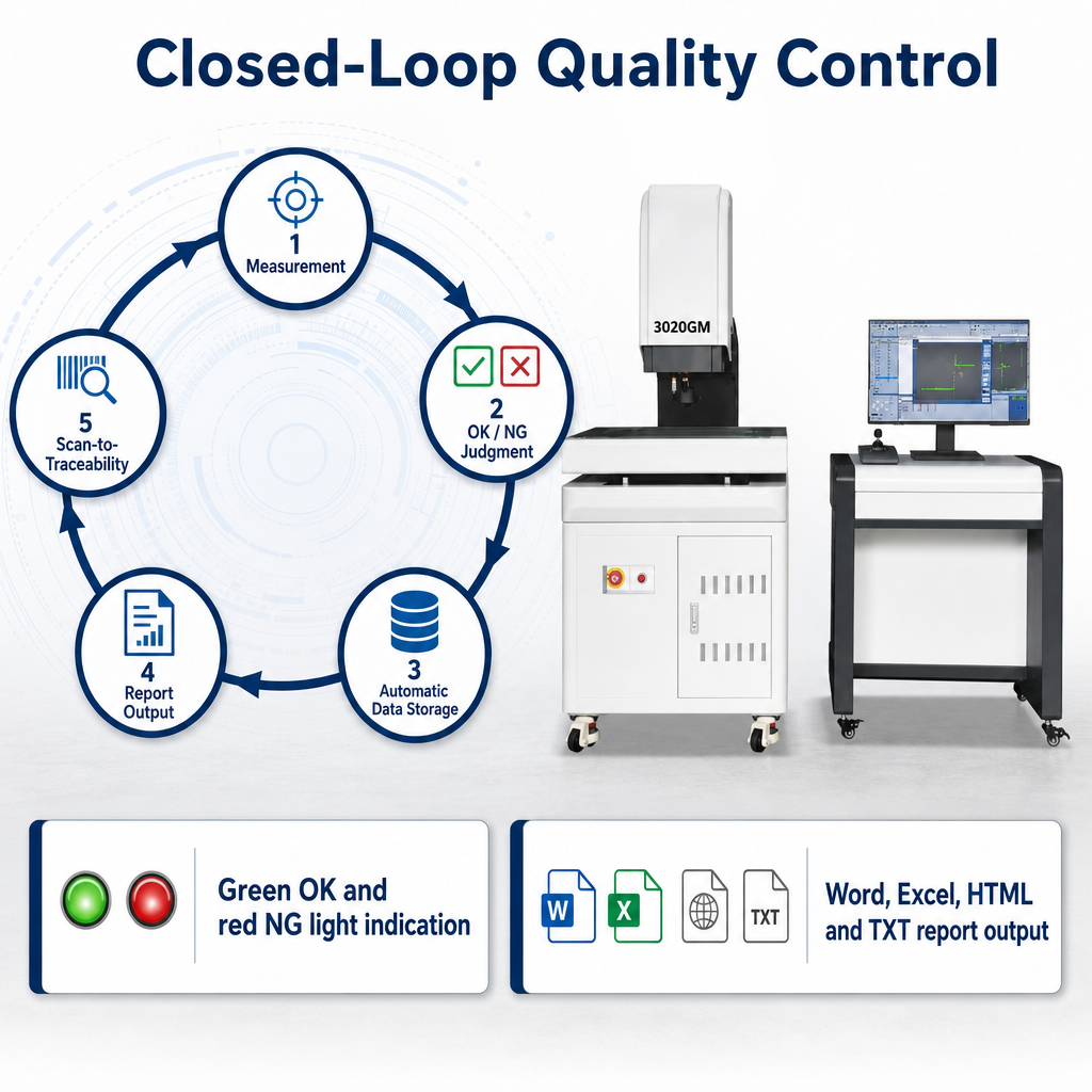
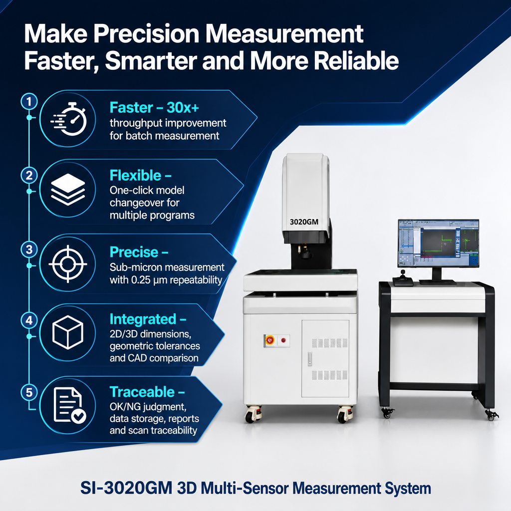
Operation & Data Generate measurement tasks for fully automatic batch measurement; automatic and manual interactive operation both supported Automatic skew compensation in automatic mode Interface language: Chinese / English Pass/fail indication: green light for OK, red light for NG Automatic data logging for both conforming and non-conforming parts, stored on the industrial PC. Logged fields include test time, dimensions, thickness, flatness, warpage, arc data and OK/NG result Barcode scanning function with a network port for traceability, stored on the industrial PC
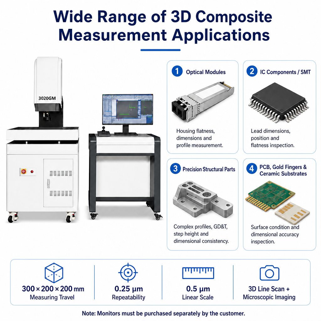
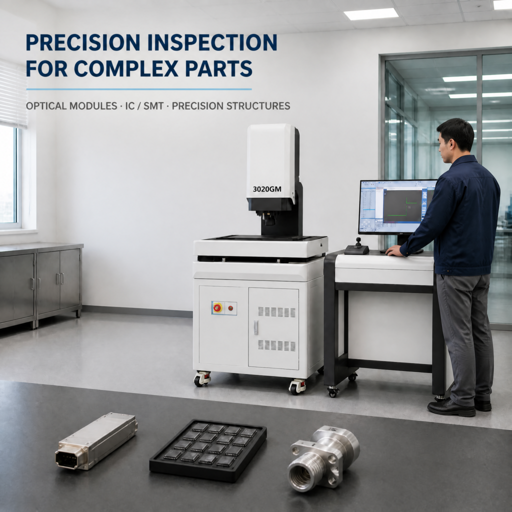
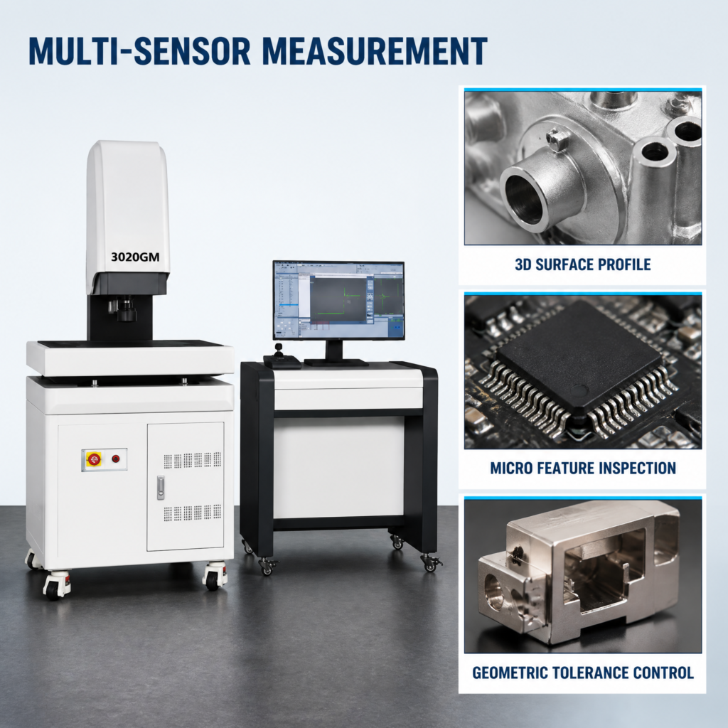
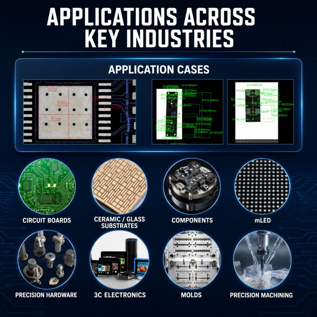
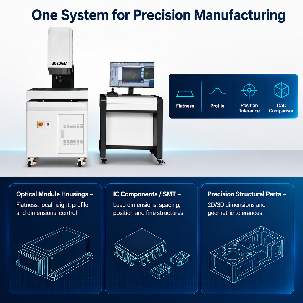
Applications Sector Typical Parts and Measurements Optical modules Housing flatness, dimensions and profile measurement IC components / SMT Lead dimensions, position and flatness inspection Precision structural parts Complex profiles, GD&T, step height, dimensional consistency PCB, gold fingers & ceramic substrates Surface condition and dimensional accuracy inspection xLED modules Dimensional and positional inspection Circuit boards (rigid and flexible) Full-dimension inspection Precision machining & hardware Geometric and form tolerance verification Automotive · semiconductor · electronics Incoming and in-process dimensional control Moulds · optical processing · medical Profile and tolerance verification
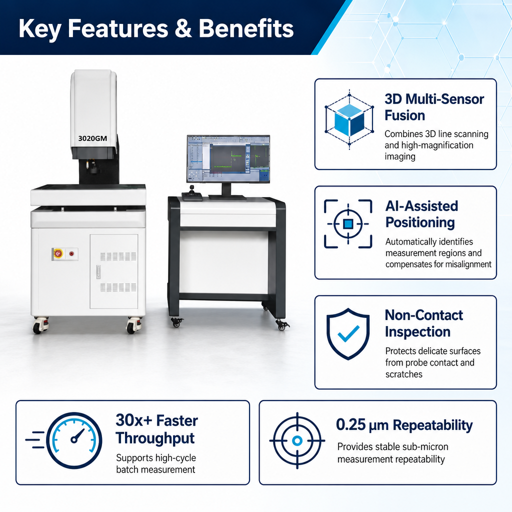
Documented application example. Optical module housings must hold overall flatness across 21 defined positions, because surface undulation degrades heat dissipation. Conventional contact-probe methods are slow and can scratch the surface. Using 3D line scanning combined with high-magnification imaging and AI-assisted location of the measurement regions, all 21 flatness points are measured without contact, tolerances are imported automatically from the CAD model, and a graphical report is generated.
Key Features
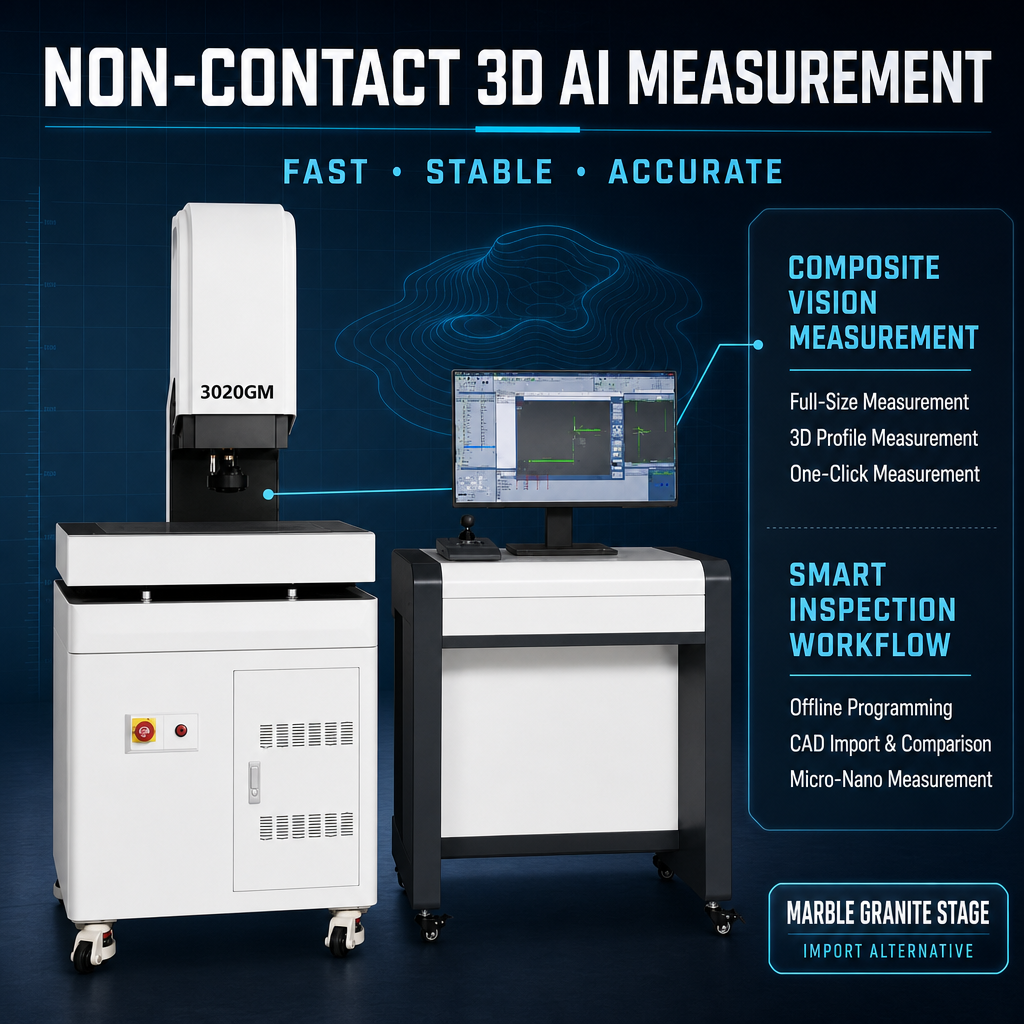
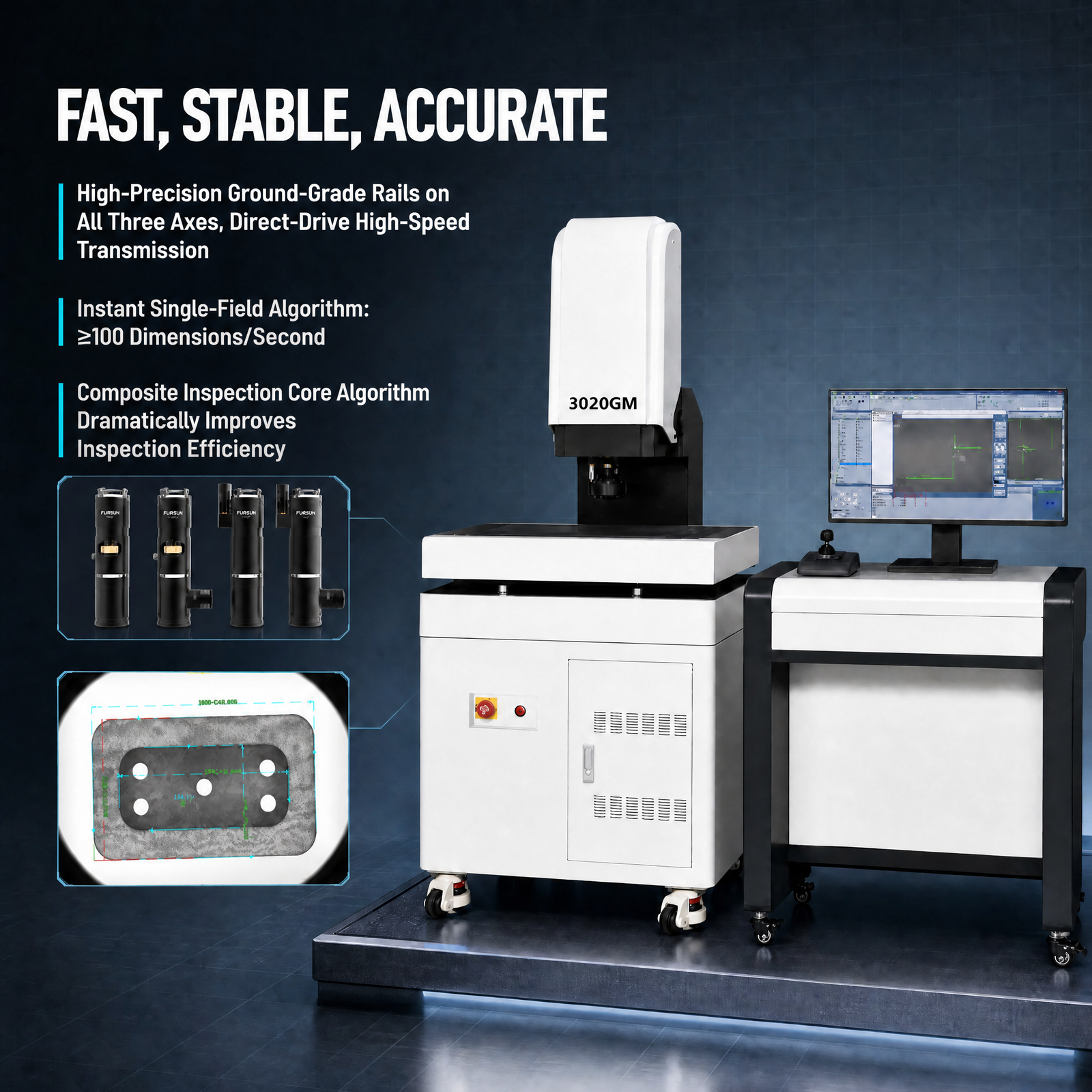
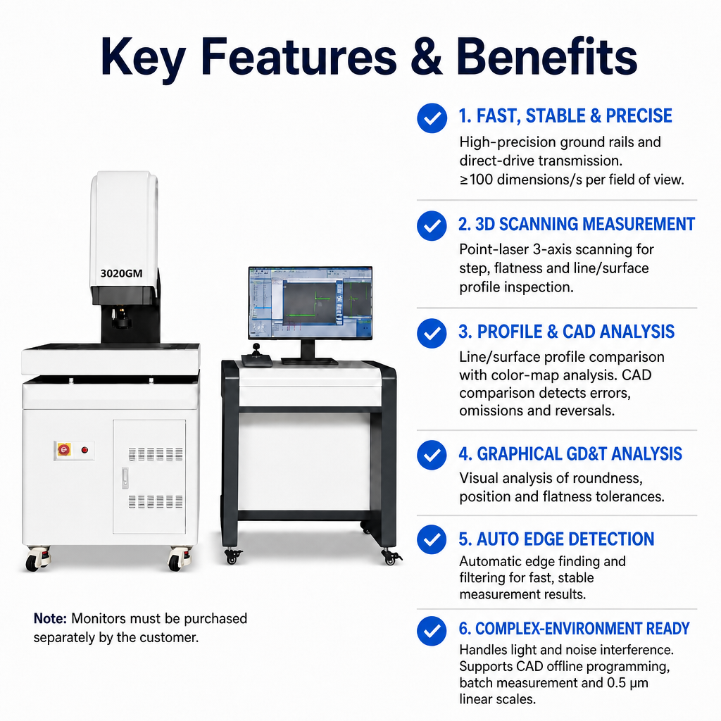
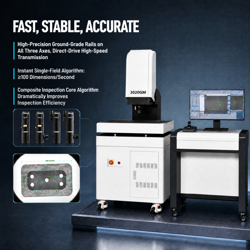
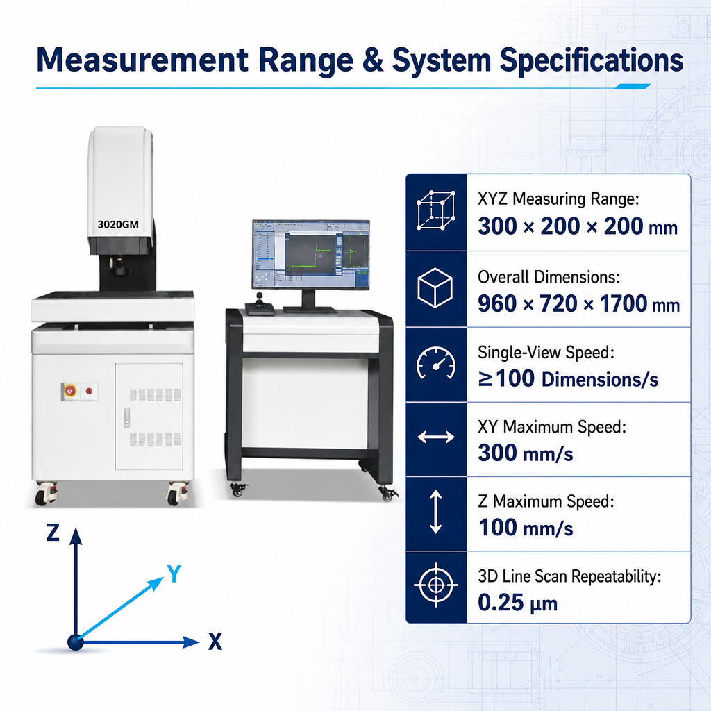
Fast, Stable and Precise All three axes run on precision ground linear guides with direct-drive transmission. The single-field-of-view fast algorithm resolves ≥ 100 dimensions per second, and the composite detection core algorithm substantially raises overall throughput versus sequential 2D-then-3D workflows.
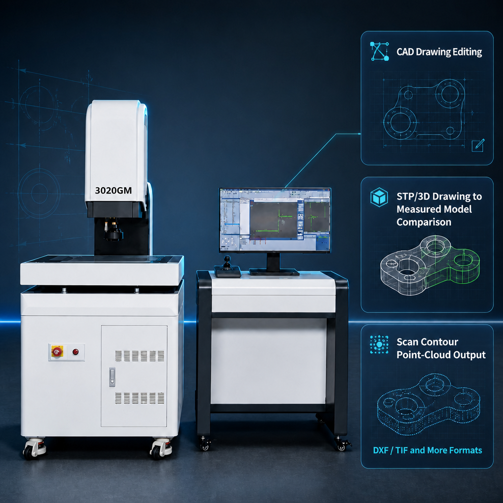
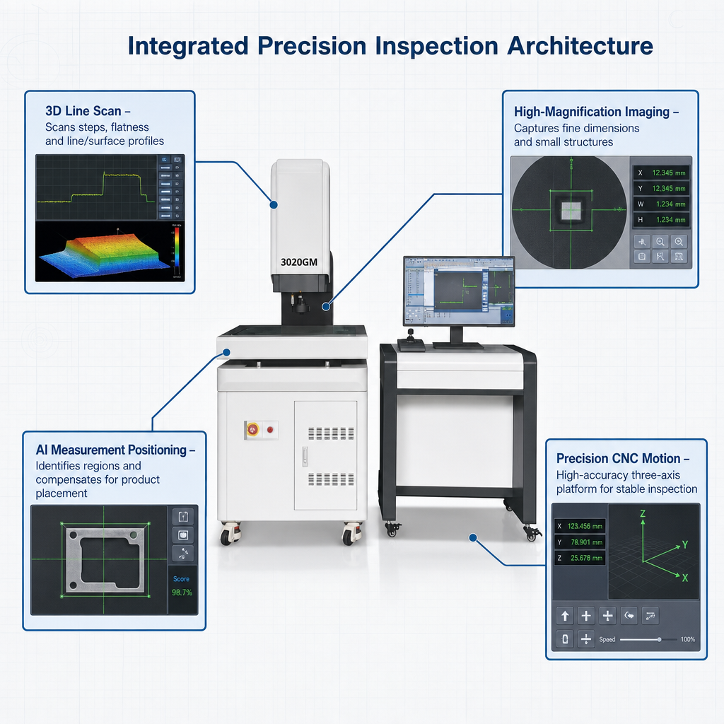
True Composite 2D + 3D Sensing Two measurement channels work on the same part, in the same coordinate frame:
Optical channel — a 2.3 MP high-definition colour digital CCD behind an auto-zoom coaxial lens (0.7–4.5X lens magnification, 20–180X image magnification), plus a wide-field navigation lens for fast part location. 3D channel — a line-scan laser profiler with 60 mm working distance, 30 mm single-field X width, 3200 X-profile points and a 3200–64000 Hz scan rate, delivering 0.25 μm 3D repeatability. Three-axis laser scanning measures step height, flatness and line/surface profile tolerance, and supports CAV comparison with automatic detection of errors, omissions and reversals.
Integrated Profile Tolerance Module Line profile and surface profile tolerance are handled in one integrated module. Contour data is aligned and compared automatically, and the system outputs both the numeric profile tolerance value and a colour-scale comparison graphic — so a deviation trend that would take an engineer an hour to interpret from a number table is visible at a glance. Precision mathematical algorithms and advanced image processing suppress error and interference sources to protect result accuracy.
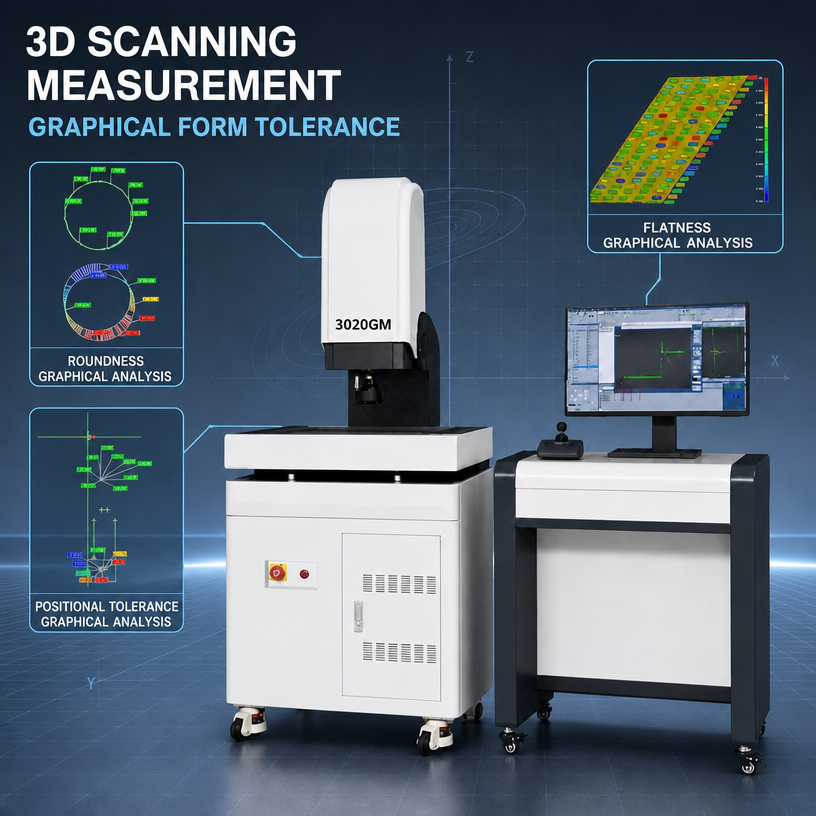
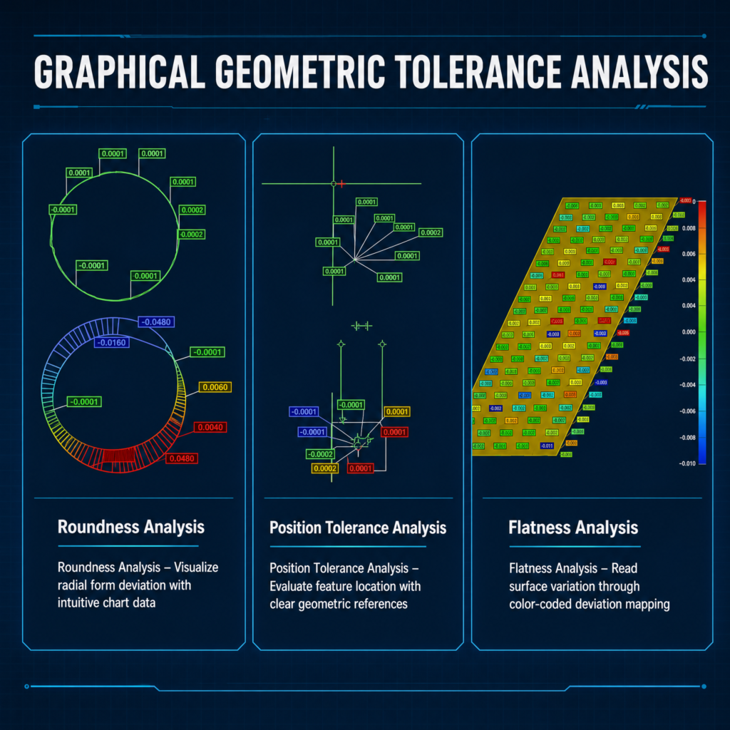
Graphical GD&T Analysis The instrument integrates geometric tolerance measurement with conventional 2D/3D dimensional work. Supported geometric tolerances include straightness, roundness, position, parallelism, perpendicularity, inclination and concentricity, with dedicated graphical analysis for roundness, position and flatness.
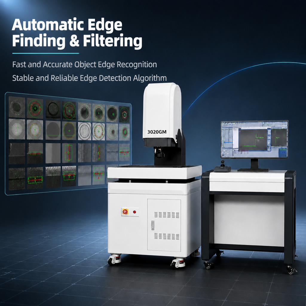
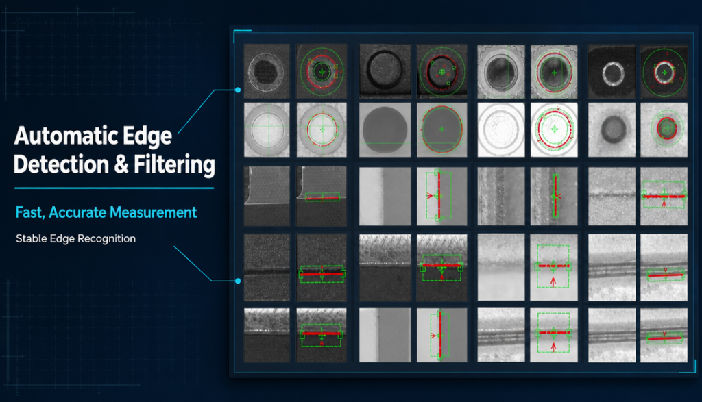
Automatic Edge Detection and Filtering Object edges are identified automatically and accurately within the image, using a stable, repeatable edge detection algorithm. This removes operator-to-operator variation from the result and keeps measurement consistent across shifts.
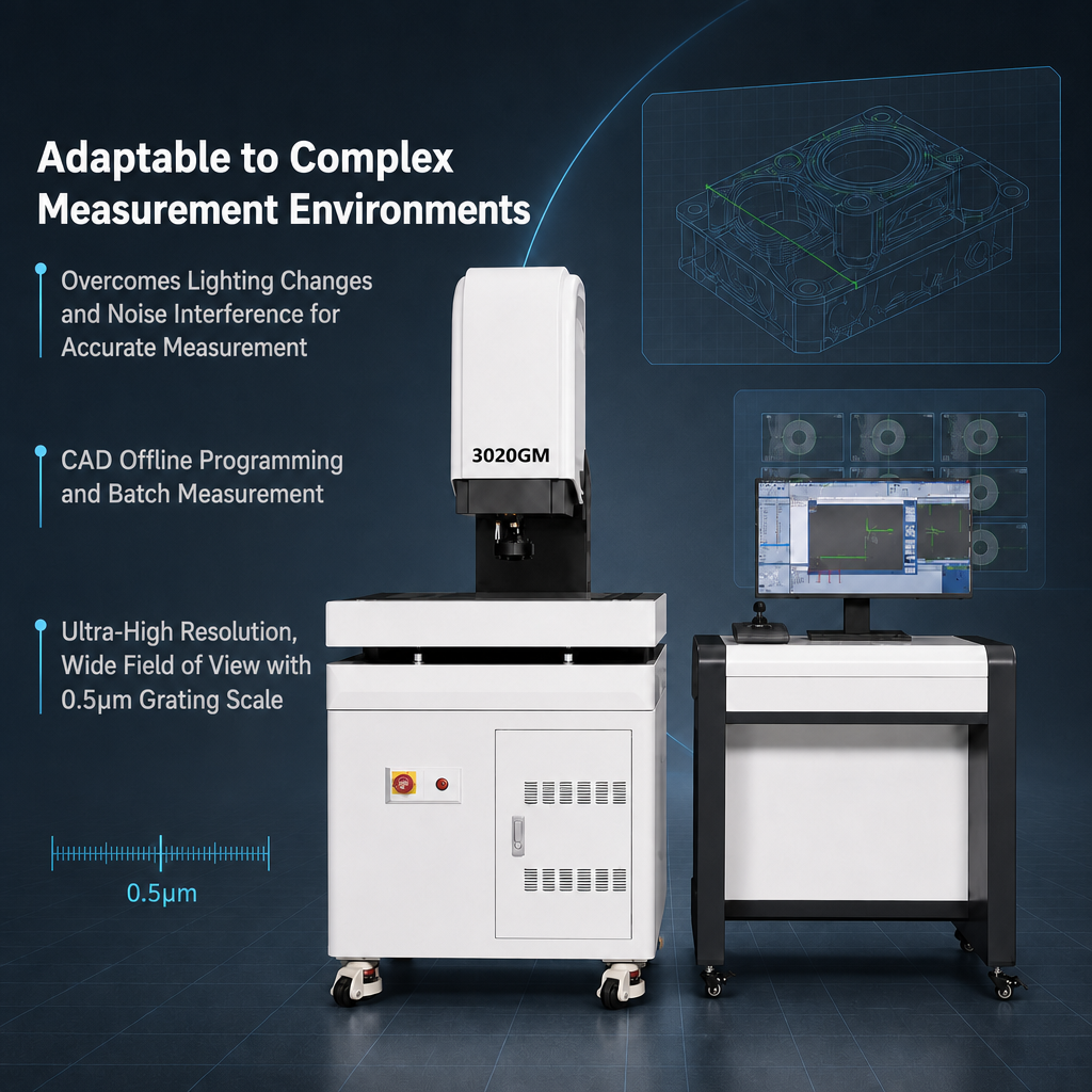
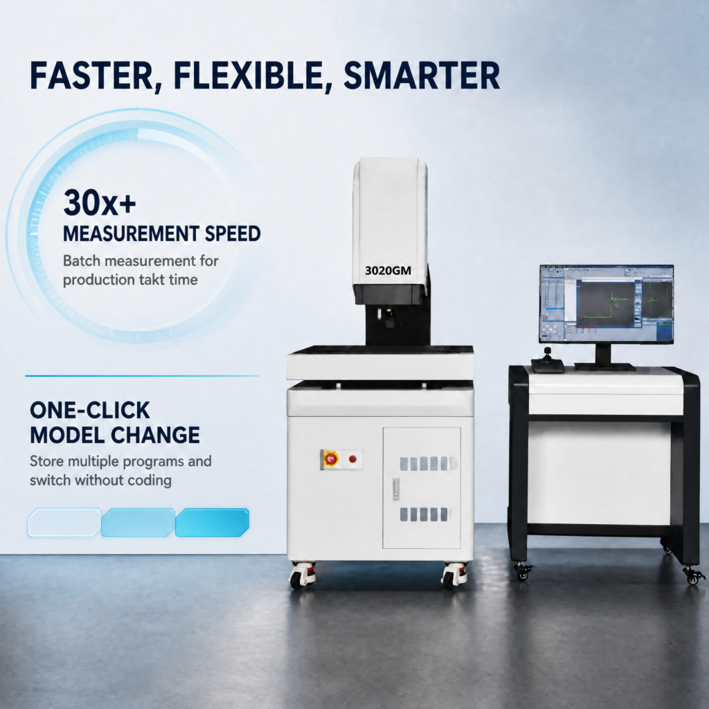
Built for Real Production Environments The system is designed to overcome illumination variation and image noise. It supports CAD offline programming for batch measurement, and a super-high-resolution wide field of view backed by 0.5 μm linear scales. In automatic mode, a part placed at an angle is compensated and corrected automatically — operators do not need to fixture parts precisely.
Why Choose Us
Product Documents
Shengmei Instruments SI-3020GM Three-dimensional Composite Image Measuring Instrument Technical Specification
Technical Specification of Shengmei Instruments SI-3020GM (2D+3D) Three-dimensional Composite Image Measuring Instrument
Shengmei Instruments_Contactless 2D&3D High-precision AI Measurement 202608
Key Features
Product Details
FAQ
Q1. What is a 3D composite image measuring instrument?
Q2. How is this different from a conventional optical/video measuring machine?
Q3. How is this different from a touch-probe CMM?
Q4. What does "composite" mean here?
Q5. What geometric features can it measure?
Q6. Is there graphical GD&T analysis?
Q7. Can it measure flatness and step height?
Q8. Can I import my CAD drawings?
Q9. What data is logged automatically?
Q10. What industries is this machine used in?
Q11. Can you give a concrete application example?
Q12. Do you support OEM / ODM and customisation?

Interested in This Product?
Tell us your project details and our team will prepare a customized quotation.
GET QUOTE NOW