
Preventing wrinkles during polarizer film lamination starts with identifying when the film first loses stable support or contact—not by increasing roller pressure immediately. Record the wrinkle direction relative to the feeding direction, its position on the substrate, and whether it appears during handling, liner removal, initial contact or the roller stroke. These observations help distinguish material deformation from feeding, alignment, substrate support and roller-contact problems. A polarizer laminating machine must also be evaluated against the actual film, adhesive, substrate and fixture arrangement. Process settings should be confirmed through supplier guidance and representative sample testing rather than transferred from another display application.
Read the Wrinkle Pattern Before Changing Settings
The first decision is whether the wrinkle originates in the incoming material, develops while the film is being positioned, or appears as the bonding front moves across the substrate. These are different process conditions, even when the finished defect looks similar.
Start by comparing the wrinkle’s orientation with the film-feeding direction. In the table below, longitudinal wrinkles run parallel to the feed path, while transverse wrinkles run across it. These patterns provide useful starting points for troubleshooting, not fixed fault codes. The same appearance can result from different combinations of film tension, alignment, substrate support and roller contact, depending on the material format and machine configuration.
| Wrinkle pattern | Possible contributing conditions | First area to examine |
|---|---|---|
| Longitudinal | Uneven film tension, feeding resistance, film skew or inconsistent support. | Film path, unwind condition and edge movement. |
| Transverse | Uneven liner release, local slack or inconsistent initial contact. | Peeling path and the leading-edge bonding condition. |
| Diagonal | Film skew, positioning variation or uneven substrate support. | Reference edges, fixture position and film registration. |
| Local folds or puckering | Existing material damage, local obstruction or an unsupported area. | Film condition, substrate surface and local contact. |
Timing matters just as much as direction. A crease visible before loading points toward material condition or handling. A wrinkle that develops when the liner is removed suggests a feeding or support issue. If the film looks flat before contact but folds as the roller advances, investigate the substrate holding and contact sequence.
There is also a useful distinction between a defect that follows the material and one that follows the machine. If the defect moves with different sections of a film roll, examine the material and unwind conditions. If different samples repeatedly develop a wrinkle at the same machine-side location, the fixture, support surface or roller arrangement deserves closer attention.
Do not diagnose from appearance alone. Photograph the defect before making adjustments, mark its direction relative to the feeding path, and record the stage at which it first appears. This creates a more useful reference than simply recording that a panel has wrinkles.
Where the pattern suggests film skew or inconsistent registration, it is also worth reviewing the alignment methods for optical film application. A positioning problem should be separated from a wrinkle introduced during the actual bonding stroke.
For production teams evaluating a different handling arrangement, the available film laminating machines provide a starting point for comparing roller-based application, substrate holding and local dust-control configurations. The appropriate machine still depends on the material stack and the actual defect being investigated.
How Do Film Handling and Liner Release Affect Feeding?
A polarizer can develop deformation before it reaches the roller. This is easy to overlook when troubleshooting focuses only on machine settings, particularly when the incoming material looks acceptable while still protected by its release liner.
Roll-fed film and pre-cut sheets need different checks
With roll-fed polarizer material, the relationship between unwind resistance and film tension deserves attention. Excessive resistance can pull the film unevenly or introduce stretching, while insufficient feeding control can leave slack that becomes visible as the material enters the bonding area.
Neither condition can be corrected reliably by simply increasing roller pressure. The feeding path, roll condition and material handling arrangement need to be examined first. If the same section of material repeatedly shows distortion before bonding, check the incoming roll and its storage history against the supplier’s handling requirements.
Pre-cut sheets introduce a different concern. A large flexible sheet can bend when lifted, repositioned or temporarily stored without adequate support. Manual correction at one edge may also create a local tension difference across the remaining sheet.
The practical distinction is whether the film stays flat and dimensionally stable throughout loading. If it already has a crease or visible deformation before entering the machine, changing the roller setting is unlikely to address the original cause.
Liner release can change how the film behaves
The release liner protects the adhesive surface, but its removal is part of the material-handling process. If the liner is pulled unevenly or too abruptly, the flexible film may move, curl or lose its intended position before it reaches the substrate.
For larger sheets, the unsupported portion is particularly important. If one section is peeled away while the rest of the film hangs freely, the sheet may bend under its own weight. A stable support arrangement helps maintain the film position while the exposed adhesive is prepared for contact.
Keep the peeling direction and handling method consistent, and follow the release conditions specified by the material supplier. Avoid touching the exposed adhesive or leaving it unnecessarily exposed during preparation.
One important distinction: liner release and roller pressure are separate process variables. A wrinkle introduced during peeling should be investigated at the material-handling stage, rather than treated as evidence that the roller needs more pressure.
Where Can Support or Roller Contact Introduce Wrinkles?
A film can enter the bonding area without visible distortion and still develop a wrinkle once contact begins. At this stage, the condition of the substrate, the fixture and the roller’s contact path become more important than the incoming film alone.
Substrate flatness affects the bonding front
The substrate needs stable support throughout the lamination stroke. If a panel is warped, incorrectly seated or insufficiently supported near an edge, the film may not meet the substrate consistently as the roller advances.
Check whether the working surface is clean and whether the fixture supports the intended bonding area. Unsupported overhang, uneven contact points or particles underneath the substrate can affect how the panel sits before lamination begins.
Where vacuum holding is used, examine whether the film and substrate remain stable during the complete holding and release sequence. Vacuum adsorption can help secure flexible material, but its presence alone does not prove that every area is supported correctly. The actual vacuum coverage and fixture arrangement need to suit the material and substrate geometry.
For panels with cutouts, curved profiles or unsupported areas, fixture geometry also deserves attention. Our guide to fixture design for flat, curved and irregular displays explains how support zones, locating references and clearance affect assembly stability during bonding.
Roller contact should remain consistent across the working area
A roller creates a moving contact line rather than pressing the entire film surface simultaneously. This progressive contact is useful for managing how the bonding front advances, but it also means that alignment and support conditions matter throughout the stroke.
If the roller is not parallel to the intended working surface, one side may contact the material earlier than the other. A damaged or contaminated roller surface can also create a local variation in contact. These conditions should be checked before attempting to compensate through higher pressure.
Pay particular attention to the beginning of the stroke. If the film moves or folds as the first section contacts the substrate, investigate the initial positioning, film holding and roller engagement sequence. A problem that develops at the leading edge may not be caused by the same condition as a wrinkle appearing halfway through the stroke.
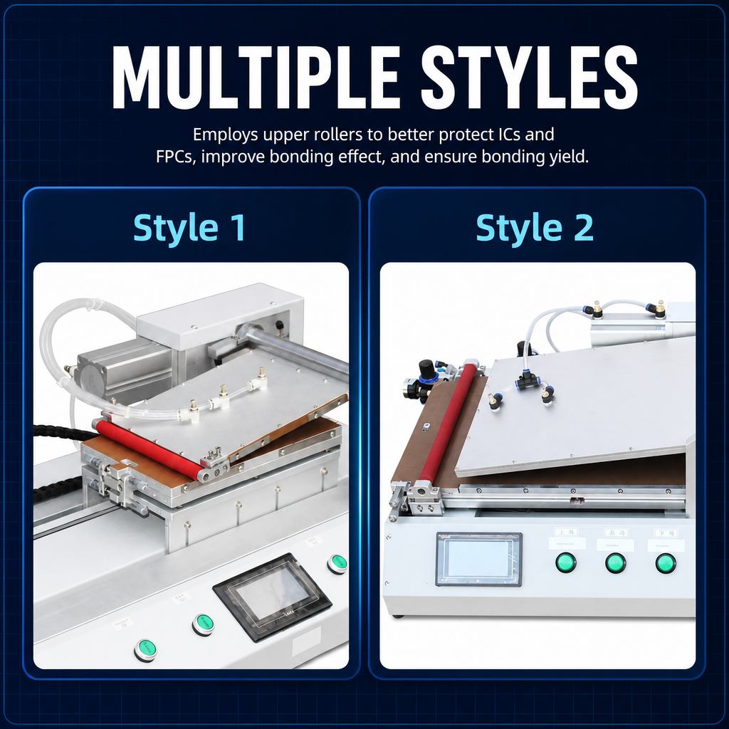
ROLLER-BASED FILM APPLICATION
9TU-M068H Upper Roller Film Laminating Machine
The 9TU-M068H is a relevant configuration to examine when the process requires progressive upper-roller contact. Its product information describes a servo-driven lower platform, dual vacuum adsorption platforms and a mechanically referenced corner-positioning arrangement.
These design elements make it worth evaluating where film holding, substrate positioning and roller contact are central to the application. The actual pressure conditions, roller configuration, material compatibility and substrate requirements must still be confirmed with representative samples.
View 9TU-M068H Details →Particles require a separate investigation. A trapped particle can create a raised area that resembles a local wrinkle, but increasing pressure does not remove the solid obstruction. Inspect the affected area under suitable lighting or magnification before deciding whether the issue is mechanical deformation or contamination at the bonding interface.
How Should One Variable Be Tested at a Time?
Once the likely source has been identified, controlled testing is more useful than making several machine adjustments at once. If film tension, liner release and roller pressure all change during the same trial, there is no reliable way to determine which change affected the result.
Start with a representative material and substrate combination. Record the original condition, including the wrinkle direction, location, material batch and the point at which the defect appears. Keep the loading arrangement and inspection method consistent so that the next sample can be compared against the baseline.
Document the film, substrate, feeding direction and existing defect pattern.
Investigate feeding, liner release, support or roller contact separately.
Check whether the wrinkle disappears, shifts position or develops differently.
Record the conditions and acceptance result before approving a process change.
For example, if film feeding is suspected, change the relevant feeding condition while leaving the roller setup unchanged. If the wrinkle is introduced during liner removal, keep the machine conditions consistent and compare the release method instead.
When roller contact is the suspected source, examine alignment and contact consistency before changing pressure. Any pressure or temperature adjustment must remain within the limits established for the actual equipment and material supplier’s specifications.
A useful process-validation record
Film / substrate identification → feeding direction → wrinkle location → tested variable → sample inspection → acceptance decision
Do not accept a change simply because one sample looks better. Check whether the defect has actually disappeared rather than moved to another area, and whether any new deformation or surface damage has appeared. The acceptance criteria should come from the display drawing, material specification and agreed process requirements.
Where the result remains inconsistent, return to the baseline and investigate whether more than one contributing condition is present. The aim is to establish a repeatable cause-and-effect relationship, not to find a machine setting that temporarily hides the defect.
When Should the Material or Tooling Be Held?
Some conditions should be treated as material or equipment issues rather than process-adjustment opportunities. Repeatedly running damaged film or using tooling with an unresolved contact problem can make troubleshooting more difficult and introduce additional variation into production.
Material evaluation
Hold the polarizer film
Incoming material should be reviewed before processing when it shows:
- Permanent creases or sharp folds.
- Visible deformation that remains after permitted handling.
- Damage to the protective release liner.
- Adhesive contamination or surface damage.
- Storage or handling conditions outside supplier requirements.
Equipment evaluation
Hold the tooling for inspection
Pause the affected setup when different samples repeatedly show:
- Wrinkles in the same machine-side location.
- Uneven roller contact across the working width.
- Movement caused by unstable substrate support.
- Visible contamination or damage on contact surfaces.
- Inconsistent fixture seating or holding conditions.
A polarizer with permanent deformation should not automatically be returned to production because the visible crease appears less pronounced after handling. The adhesive condition and functional surface may still be affected. Reuse should be decided against the material supplier’s acceptance criteria and the finished display’s requirements.
Equipment selection becomes relevant when the existing support, feeding or contact arrangement cannot maintain the required process condition. The decision should be based on the complete display stack, rather than the assumption that a larger roller or higher pressure will resolve every wrinkle.
Consider the working environment as a separate requirement
Contamination can contribute to local bonding defects, but dust control and wrinkle control are not interchangeable. An FFU can provide filtered airflow over an exposed work area; it does not correct uneven film tension, damaged material or misaligned roller contact.
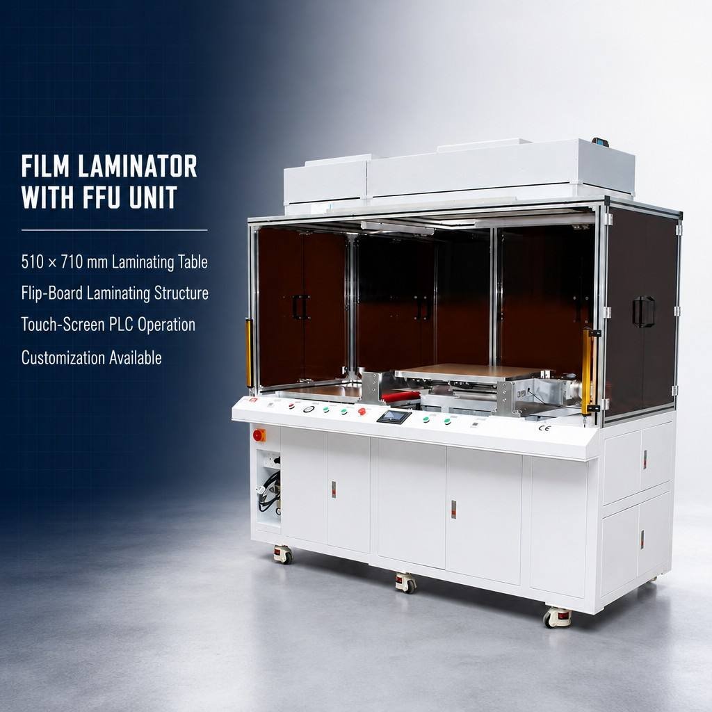
DUAL VACUUM HOLDING AND LOCAL AIRFLOW
510×710 Film Laminating Machine with FFU
The 510×710 configuration uses dual vacuum adsorption platforms: the upper suction plate holds the film during alignment and the flip phase, while the lower suction plate holds the rigid substrate during the lamination stroke. This arrangement is relevant when troubleshooting points to film movement or inconsistent holding. The holding sequence and fixture setup should still be validated with the actual polarizer format and substrate.
The overhead FFU provides filtered clean-air flow over the open bonding work area, helping control airborne contamination during film application. It does not correct uneven film tension, inconsistent liner release or roller-contact problems, and it should not be treated as a substitute for room-level cleanroom requirements.
View 510×710 FFU Details →Before selecting either configuration, confirm the complete substrate dimensions, polarizer format, film handling method, required positioning approach and actual bonding conditions. The roller arrangement, pressure requirements and material suitability should be reviewed against representative samples. A product description alone is not a substitute for application validation.
What to prepare for an equipment review
- Substrate dimensions and material type.
- Polarizer film specification and supply format.
- Complete material stack, including adhesive and release liner details.
- Photographs showing wrinkle direction and location.
- The stage at which the defect first appears.
- Existing fixture, substrate support and roller arrangement.
- Current feeding and liner-release method.
- Required output and any installation constraints.
Frequently Asked Questions
Can trapped particles resemble a wrinkle?
Yes. A particle between the polarizer and substrate can create a local raised area that resembles a fold. Inspect the affected area under suitable lighting or magnification. A particle-related defect requires contamination control, while an actual wrinkle requires investigation of film deformation and contact conditions.
Should roller pressure be increased first?
No. Check film tension, liner release, substrate support and roller alignment before changing pressure. Pressure adjustments should only be made through controlled sample testing and within the limits confirmed for the actual material and equipment configuration.
When is a damaged polarizer unsuitable for reuse?
A polarizer with permanent creases, damaged adhesive, contamination or deformation outside the supplier’s acceptance limits should be held for evaluation. A visible fold becoming less noticeable does not prove that the material remains suitable for production. Follow the supplier’s specifications and finished-display acceptance requirements.
POLARIZER FILM LAMINATION · APPLICATION REVIEW
Review the Film, Substrate and Roller Configuration Before Production
Preventing wrinkles starts with identifying the stage where the film loses stable contact. Record the wrinkle direction and occurrence point, then investigate material condition, substrate support, film feeding and roller contact separately.
If the current process continues to produce defects, share the actual display stack, representative wrinkle photographs and the stage at which the defect first appears. These details give JiuTu a more useful basis for reviewing the film-holding, substrate-support and roller configuration and deciding whether sample validation is needed.