
The shape of a display assembly is only the starting point for designing its tooling. What matters is how the finished stack can be supported and located without putting unnecessary stress on vulnerable areas. A flat panel may sit on a broad reference surface, a curved stack needs support that follows its profile, and an irregular assembly may rely on a few stable locating points with enough relief around cutouts and connectors.
On a vacuum laminating machine, fixture geometry also affects how the assembly is loaded, how much clearance remains during pressing and whether air can escape as intended. These decisions are easier to make when the complete assembly is considered, rather than judging the tooling from the panel outline alone.
Start With the Unsupported Areas of the Assembly
A display assembly can look straightforward on a drawing: a rectangular cover glass, a bonding layer and a module underneath. The underside, however, often tells a different story. A recessed component, flexible circuit or unsupported section can change how the stack meets the fixture and where the load travels when the press closes.
Consider a cover glass that sits neatly on a flat fixture while a connector housing extends below the module. The connector may make contact before the surrounding glass is properly supported. Applying more pressure will not correct the mismatch. It simply transfers additional load to a feature that may never have been designed to carry it.
This is why the distinction between permitted support areas and no-contact areas matters so much. Cable exits, raised components, sensitive surfaces and unsupported spans may all need clearance. Bonding boundaries and dimensional tolerances matter as well, because the nominal CAD shape is not necessarily the exact geometry encountered during production.
Once the contact areas are understood, the usable working area and tooling envelope of OCA vacuum laminating machines can be considered in context. The relevant footprint is not just the visible panel, but the complete stack and any carrier or fixture required to hold it safely.
How Do Flat, Curved and Irregular Parts Change Support?
Different display geometries create different support problems. A fixture that works well for a flat panel may be unsuitable for a curved assembly, even when both products have similar overall dimensions. The difference comes down to where contact occurs and how the assembly behaves under load.
Flat parts: a reference plane is useful only when the stack is supported
A flat display often appears to be the easiest case. A stable reference plane can support the assembly while approved edges or locating features keep it in position. But a flat cover glass does not guarantee a completely flat underside. Local bow, changes in stack thickness or components beneath the module can leave parts of the assembly at different heights.
That makes the choice between broad contact and localized support more important than the panel’s appearance. Broad support may suit an assembly with a sufficiently consistent underside, while defined support regions may be more appropriate when sensitive components or recessed areas are present. The right arrangement depends on the contact map, part tolerances and how a representative assembly behaves under the intended load.
Curved parts: the cradle should follow the product, not reshape it
Curved displays introduce a different challenge. A flat fixture may touch the panel at only a few points, leaving other sections suspended. A contoured cradle can provide a closer fit, but matching a nominal radius is not always enough. Some assemblies have curvature that changes across their width or length, so a support that looks correct in a two-dimensional drawing may still create unwanted contact when viewed in three dimensions.
The more reliable reference is the actual three-dimensional profile, including its permitted variation. A cradle should follow the intended geometry without forcing the assembly into a different shape. This is particularly important when the pressing load is applied, since small contact mismatches can become more significant under pressure. Curved-display compatibility therefore needs to be demonstrated for the specific tool and stack, rather than assumed from a laminator’s general application list.
Irregular parts: locating and supporting are different jobs
Notches, angled sides, asymmetric edges and cable exits make irregular assemblies harder to locate with a conventional perimeter fixture. Trying to constrain every edge can actually introduce more problems, particularly when some edges are cosmetic, flexible or subject to dimensional variation.
A better arrangement may use a small number of approved datums to establish position, while separate contact surfaces carry the assembly’s weight and pressing load. For example, an assembly with a corner cutout and flexible tail may not be well suited to locating against the cutout itself. A stable reference edge and another approved feature can provide more consistent registration, while the fixture leaves clearance around the cutout and cable.
The important distinction is that the surfaces responsible for positioning the part do not necessarily need to be the same surfaces that support it. Keeping these functions separate gives the fixture more room to accommodate irregular geometry without placing unnecessary restrictions on the assembly.
Where Should Datums and Clearance Be Defined?
Once the support areas are understood, the next question is how the assembly will return to the same position every time. This is where locating datums become important. A datum should represent the feature that controls the finished assembly’s position, not simply the easiest edge for an operator to push against.
For example, a cosmetic outline may vary independently of the optical bonding area. If that outline is used as the only reference, its variation can carry through to the finished alignment. A designated support plane and approved edge references may be sufficient for a flat stack, while curved and asymmetric assemblies often need a more carefully considered reference arrangement. Flexible cables and decorative edges are rarely suitable substitutes for stable mechanical references.
This also connects fixture design to the wider bonding process. Our guide to alignment methods for optical film application explains the differences between manual and camera-assisted positioning. Whichever method is used, repeatable alignment still depends on having a consistent reference on the workpiece.
Clearance can be just as important as positioning accuracy. A cable might fit comfortably inside a machined pocket once the assembly is seated, yet catch against the pocket wall during insertion. A connector may sit below the platen at rest but obstruct the movement needed to load or remove the part. With curved assemblies, the same problem can be harder to spot because a recess that looks generous from above may be too shallow or narrow in three dimensions.
A useful way to review a tooling drawing: look at the assembly both in its final seated position and along its loading path. The second view often reveals problems that are easy to miss in a static CAD image, particularly around cables, connectors and curved edges.
How Can Tooling Interfere With Loading and Vacuum?
A fixture can be accurate in its final position and still be awkward to use. An outer locating wall may catch the edge of an irregular panel during insertion, while a deep curved cradle may leave too little room to reach the assembly during removal. If the operator has to flex the display just to get it into place, the tooling is already creating a process risk.
Vacuum behavior is another part of the picture. Depending on the chamber design and bonding sequence, tall fixture walls or enclosed recesses may affect how air is evacuated around the stack. That does not mean every fixture needs machined vacuum channels. It means the actual fixture geometry should be considered as part of the machine’s vacuum setup, rather than assuming that the machine’s published vacuum specification guarantees the same result with every tooling arrangement.
For larger industrial assemblies, the 850×1350mm Vacuum Laminating Machine provides a relevant equipment reference. Its published working format makes it useful when considering a large panel together with its carrier and fixture. However, available platform space alone cannot establish whether a particular tool height, loading path or curved support will be suitable.
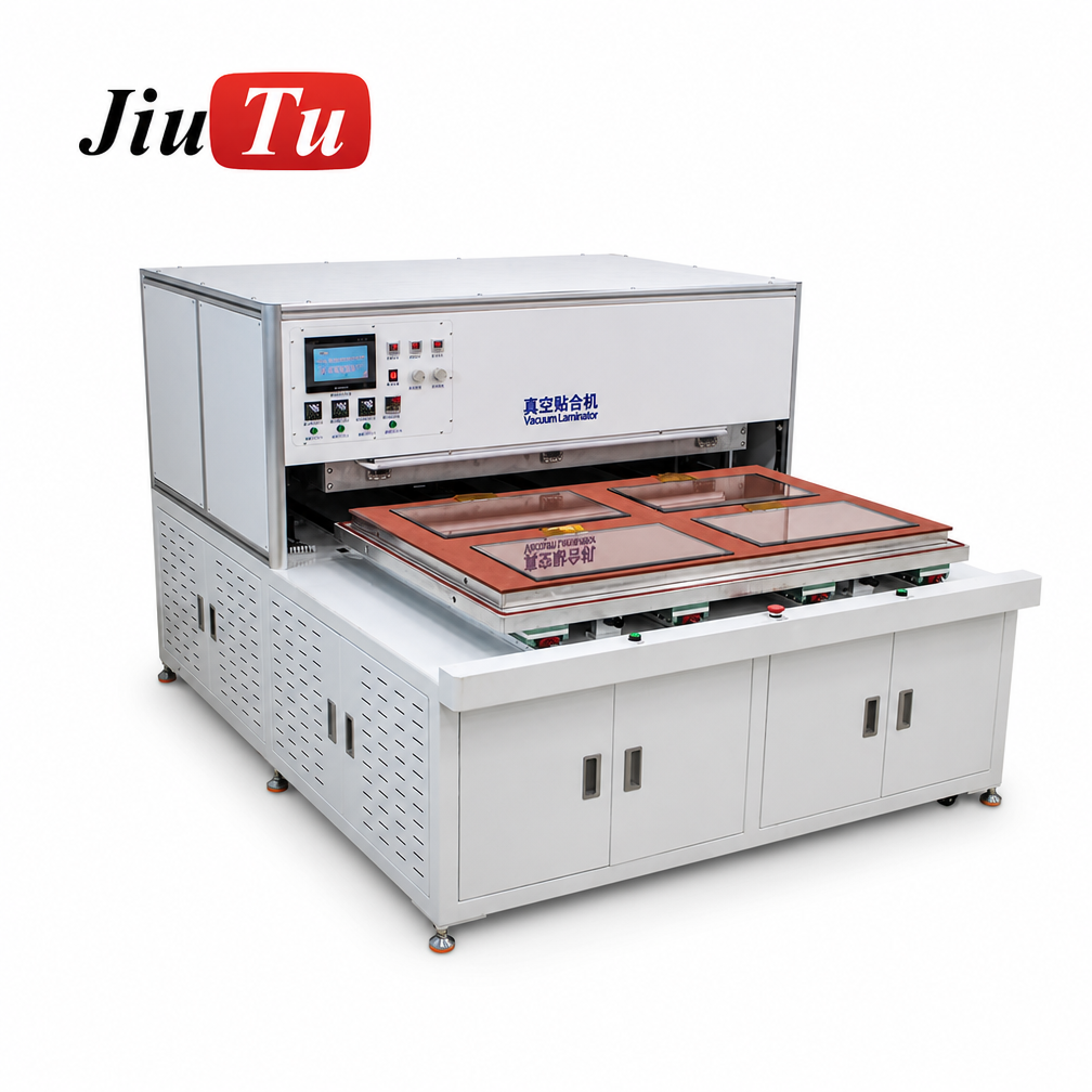
850×1350mm Vacuum Laminating Machine
When reviewing a large display assembly, the panel and its carrier need to be considered together. The loading-platform arrangement provides a useful reference, while fixture height, insertion access and the pressing sequence still need to be assessed against the proposed tooling.
View product and working format →In practice, a machine may have enough nominal working space while a particular fixture remains unsuitable for its operating movement. The equipment and process teams therefore need to consider the complete fixture envelope, loading orientation and available pressing clearance as one connected arrangement. These details can be discussed with JiuTu’s configuration team using the proposed CAD model and representative sample stack.
For a closer look at the separate question of machine sizing, our vacuum laminator working-area sizing guide explains how panel dimensions, tooling footprint and loading orientation affect the usable working area.
What Must a First-Article Trial Confirm?
CAD can show whether a fixture appears to match the intended geometry, but the first-article trial reveals how that arrangement behaves with a real display. A sample may sit correctly against its stops before pressing and then shift as the load develops. A cable that clears during insertion may become trapped during removal, or a curved panel may reveal an unexpected contact point once pressure is applied.
The loading stage is therefore worth observing as closely as the bonding cycle itself. A well-designed fixture should allow the sample to settle against its intended references without forcing it into position. Its approved support surfaces should carry the contact, rather than a raised connector, flexible circuit or sensitive display area.
After lamination, the finished assembly provides another part of the evidence. Registration, physical condition and bonding quality should be assessed against the agreed acceptance criteria. If a defect appears, it is important to distinguish between a locating problem, unexpected mechanical contact, material behavior and an issue with the vacuum or pressing sequence. A visible defect alone does not identify its cause.
Make the trial result traceable.
A useful release record connects the result to the exact setup that produced it. Include the assembly revision, locating references, fixture revision, loading orientation, equipment configuration, validated process settings and inspection findings. This makes it clear which geometry was actually tested and prevents approval from being applied to untested variations.
Where the bonding method requires staged pressure control, the 9TU-M040D Industrial Vacuum Laminating Machine is another configuration worth considering. Its published 710 × 510 mm platform and 85 mm lamination height provide mechanical dimensions to compare with the proposed fixture. Separately, its three-stage recipe controls for pressure, processing time and vacuum state are relevant to the bonding sequence. Neither the platform dimensions nor the recipe settings, on their own, establish compatibility with a particular display assembly.
9TU-M040D Industrial Vacuum Laminating Machine
The workpiece, fixture and pressing sequence all need to fit within the confirmed platform and lamination-height limits. The machine image provides equipment context, but the suitability of a specific tooling concept still depends on the actual sample and trial results.
Review the machine configuration →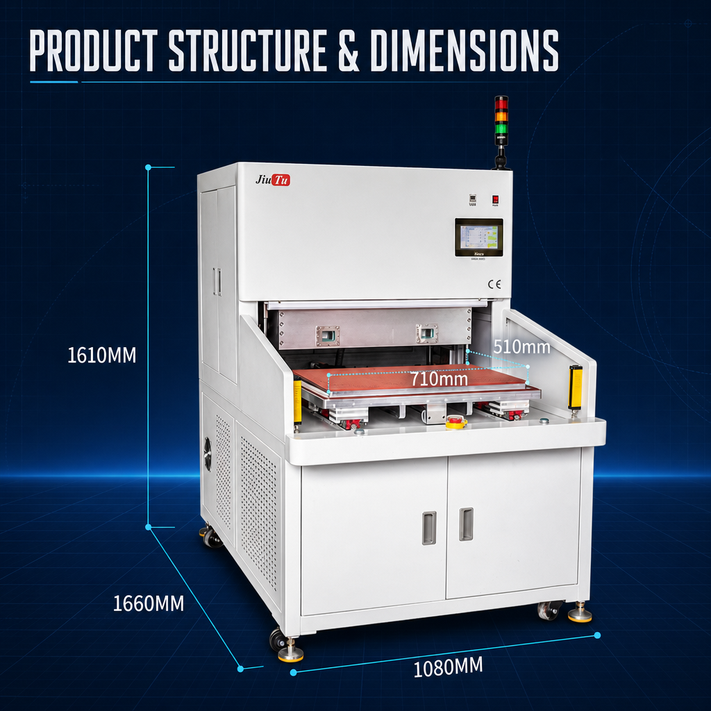
A successful first sample is a useful starting point, but it does not automatically prove that every permitted variation will load, locate and release in the same way. Where geometry or tolerances vary, the fixture needs representative trials before approval. The final result should be a documented tooling revision and a clearly defined workpiece configuration, including any limitations on curved or irregular assemblies.
Frequently Asked Questions
Can one fixture handle several geometries?
It can, provided the assemblies share compatible support areas and locating references. Interchangeable inserts or adjustable stops may make a common fixture practical, but each geometry still needs to be evaluated for contact, clearance and repeatability. A fixture validated for a flat panel should not automatically be considered suitable for a curved one.
Should active display areas be used as locating surfaces?
Active display areas should not be assumed to tolerate mechanical contact or loading. Approved mechanical datums are generally a more appropriate basis for physical location. If an optical feature is used for alignment, it is important to distinguish non-contact measurement from physical contact and follow the assembly’s documented restrictions.
What drawings should a tooling supplier receive?
A complete stack drawing is the best starting point. It should show dimensional tolerances, curvature where applicable, permitted support and no-contact zones, locating datums, cable and connector geometry, and the intended loading orientation. Three-dimensional CAD and representative samples are particularly helpful when the assembly has irregular edges or changing curvature.
Good display tooling makes the intended assembly position repeatable without asking vulnerable areas to carry unintended loads. For flat panels, that may be relatively straightforward once the support plane is understood. Curved and irregular assemblies require more attention to their three-dimensional profile, contact points and the space needed around sensitive features.
Ultimately, a fixture should be judged by how the actual assembly sits, moves and behaves during lamination—not simply by how closely its outline matches a CAD drawing. Machine dimensions help narrow the options, but curved-display tooling capability must be confirmed separately through the proposed configuration and representative samples.
Application & Configuration Review
Review the Stack and Tooling Together
If you are evaluating tooling for a flat, curved or irregular display assembly, the most useful starting point is the complete stack drawing. Sharing its layer construction, permitted support areas, no-contact regions, locating datums, curvature and cable-clearance requirements gives the equipment team a clearer basis for reviewing the fixture concept. Proposed loading orientation and sample dimensions also help establish whether the arrangement suits the intended machine configuration.