
Choosing between CCD alignment and manual alignment should start with the permitted film-placement error and the production pattern—not with the assumption that camera automation is always the better choice. Manual alignment can be practical for samples, small batches and frequently changing products when a stable fixture or panel reference edge allows repeatable positioning. CCD alignment becomes more relevant when X/Y or angular error is difficult to control visually, when panel handling creates variation, or when repeated production needs less dependence on individual operator judgment.
The useful question is therefore not “Which method is more advanced?” It is “Which method keeps the finished laminated film inside the required tolerance with acceptable rework, cycle time and changeover effort?” That should be demonstrated with representative panels and film materials.
This is particularly relevant for prototypes, low-volume work and applications where fixtures can define the film position without repeated fine correction.
Camera alignment deserves closer review when position and rotation both matter, panels are difficult to align consistently, or the same product is produced repeatedly.
What Does Optical Film Alignment Actually Need to Control?
Optical film alignment is not simply a matter of making two visible edges look parallel. The process needs a defined relationship between the film and the panel, and that relationship should come from the product drawing, an assembly specification or another agreed acceptance requirement.
The reference may be a panel edge, a fixture datum, a registration mark, a machined feature, the edge of an active display area or another feature that can be located repeatedly. Depending on the application, acceptance may involve horizontal and vertical displacement, rotational error, edge clearance, overlap between functional areas or a combination of these conditions.
Define the edge, mark or fixture feature that represents the intended panel position.
Specify where the film should sit horizontally and vertically relative to the datum.
Two edges can look visually close while the film is still rotated outside the allowed condition.
The film and substrate need to remain stable as the bonding sequence begins.
The final result matters more than the apparent position before contact begins.
For polarizer film alignment, orientation can be as important as edge location. Other functional optical films may need a cut feature, aperture or coated area to maintain a defined relationship with the LCD reference. The phrase “alignment accuracy” is therefore incomplete unless the team first specifies what feature is being measured and what feature it is being measured against.
The film itself can also introduce uncertainty. If a slit or die-cut edge varies relative to the functional area of the material, using that edge as the only reference transfers part of the film manufacturing tolerance into the lamination process. Neither a camera nor an operator can fully compensate for a datum that does not consistently represent the required finished position.
Define the pass/fail reference before comparing alignment systems. If the quality team cannot state which edge, mark or feature determines acceptance, it is too early to decide between camera alignment and manual positioning.
The positioning method must also work with the holding and lamination sequence. A film can be correctly located on the table and still move when vacuum changes, a liner is released or the first part of the film contacts the substrate. This is one reason equipment selection should consider alignment, fixture design, material holding and the bonding motion as one process rather than separate features.
Once the reference and tolerance are defined, review the alignment method together with the wider optical film laminating machine configuration. The alignment system only has value if the rest of the process preserves the corrected position.
How Does CCD Alignment Change the Film Application Process?
A CCD film laminating machine uses camera alignment to identify defined reference features before bonding. Depending on the application, the camera may locate registration marks, edges or other recognizable geometry on the substrate and film. The machine then determines the relationship between the two references and applies the required positional correction before lamination proceeds.
The main process difference is where the positioning decision is made. In a manual process, the operator interprets visible references and physically adjusts the film or fixture. In a camera-based process, image recognition provides the measured offset and the positioning system executes the correction.
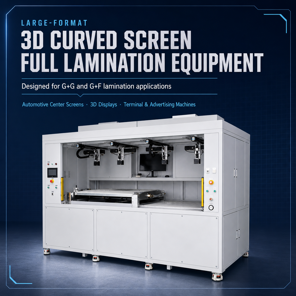
This can reduce dependence on viewing angle, hand positioning and individual operator judgment. It is particularly relevant when a small alignment change is difficult to detect visually, when both linear and angular correction matter, or when a large panel makes it inconvenient to observe several reference points at once.
What CCD can reduce
Repeated operator positioning decisions
- Visual estimation of X and Y offset on every part.
- Manual judgment of rotational correction.
- Variation caused by viewing position or individual alignment technique.
- Dependence on an operator recognizing a small offset before lamination starts.
What CCD does not remove
The need for a stable process reference
- The panel still needs a repeatable relationship to the fixture.
- The detected edge or mark still has to represent the required final location.
- Film handling can still cause stretching, curling or movement.
- The final laminated position still needs to be inspected against the acceptance requirement.
Camera alignment should not be treated as a guarantee of finished-part accuracy. Recognition quality depends on whether the feature can be detected reliably under the actual optical conditions. Transparent film, reflective glass, printed borders, low-contrast features or surface appearance changes can all affect the practicality of a vision reference. Lighting, camera view and the selected mark therefore belong in the sample qualification.
Changeover also needs practical testing. CCD can support repeatable model setups when the required references and positioning logic have already been established. A new model may still require a different reference definition, different fixture position or different recognition setup. The useful comparison is actual changeover work—not the presence of a recipe screen.
A meaningful changeover trial is to run one model, switch to another product, then return to the first. Measure whether the process returns to the previous alignment condition without excessive adjustment. This tests the relationship between fixture replacement, reference recognition, stored settings and operator setup.
When Is Manual Film Alignment Sufficient?
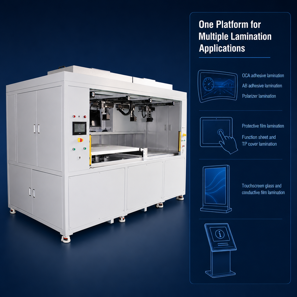
Manual film alignment does not have to mean uncontrolled freehand positioning. A well-designed manual or semi-manual process can use panel reference edges, locating stops, an adjustable fixture, vacuum holding and visual verification before the machine completes the lamination stroke.
Where these references are stable and the required tolerance leaves enough process margin, manual positioning can be straightforward and flexible. It can also reduce setup work when a production area handles many samples or models that change frequently.
This is why manual alignment for small batch optical film application remains worth evaluating. During development, the process team may need to adjust film dimensions, panel orientation or fixture position repeatedly. A physical reference can sometimes be changed more quickly than a new camera-recognition condition can be established and validated.
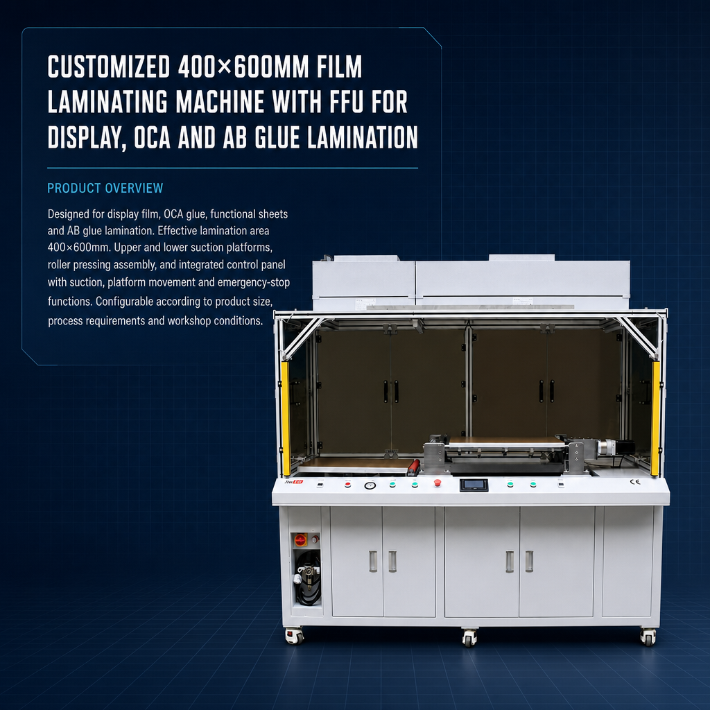
The trade-off is greater dependence on fixture condition and operator technique. Positioning results can change with loading method, visibility of the reference, how a flexible film is held and how the operator judges the final position. A process that works reliably for one experienced technician may produce a broader placement distribution when several operators run the same product.
Panel size can make that dependence more visible. On a compact part, one operator may be able to observe both reference sides at once. With a wider panel, checking one edge may require moving around the machine or changing viewing position, increasing the possibility that the film moves while another reference is being inspected.
Flexible optical material creates another practical challenge. Pulling one side to correct the position can introduce local tension or slightly change the relationship between the film edge and the actual functional area. A fixture that supports the material and reduces unnecessary hand correction can be more valuable than simply adding more visual inspection.
A good manual process removes as much judgment as practical. Clear datums, controlled film holding and a defined inspection method are more reliable than depending on an operator to judge the correct position from appearance alone.
Manual alignment is sufficient only when measured results demonstrate that it is sufficient. “An experienced operator can align it” is not the same as proving that the process can repeatedly maintain the specified finished-film position across normal operators, shifts and changeovers.
CCD Alignment vs Manual Alignment Across Four Production Scenarios
The most useful comparison comes from the production pattern. Volume matters, but it is not the only variable. Tolerance, model mix, panel geometry, fixture design and operator dependence can change the decision even when two factories produce a similar number of panels.
This is why the question “when is CCD alignment needed for LCD film lamination?” cannot be answered from batch size alone. A repeated high-volume product may not require camera correction if mechanical references provide ample tolerance margin. Conversely, a small quantity of panels may justify CCD when a critical functional layer must be placed within a demanding positional or angular limit.
- Start with the finished-part requirement. Define the actual X/Y, edge or angular condition that determines whether the laminate is acceptable.
- Identify the most stable physical reference. Determine whether the panel edge, registration mark, fixture datum or another feature best represents that requirement.
- Observe how much judgment the operator adds. If positioning depends on repeatedly “splitting the difference” by eye, the reference method may not be sufficiently controlled.
- Compare real changeover work. Measure fixture adjustment and manual setup against camera recipe selection, recognition setup and post-changeover verification.
- Choose from the measured placement distribution. Use the simpler method only when it repeatedly meets the finished-part tolerance under normal operating conditions.
This decision path also explains how alignment method affects film placement. The difference is not simply “automatic versus manual.” The important difference is where measurement, interpretation and correction take place. Manual positioning concentrates more of those tasks in the operator and fixture; CCD shifts more of the measurement and correction into the vision and motion system.
How Should Alignment Accuracy Be Validated?
The safest equipment decision comes from a representative sample test. Use actual or equivalent production panels and film wherever possible, and measure the same feature that will determine acceptance during production.
One visually good sample is not enough. Repeated cycles are needed to reveal whether variation is connected to loading, film handling, reference recognition, the fixture, the operator or the changeover process. The purpose of the test is not to create an impressive yield number. It is to understand where placement varies and whether that variation remains inside the allowed limit.
Measure the required edge distance, X/Y position or angular deviation on each inspected part.
Note repositioning, rejected laminates and the confirmed reason the alignment requirement was not achieved.
Include loading, positioning, verification and correction rather than recording only the machine stroke.
Measure adjustment, recipe or reference setup and the time needed to return to an acceptable condition.
For manual alignment, use more than one qualified operator when operator dependence matters to the decision. If one technician consistently produces a narrower offset distribution than another, that difference is useful process information. It may indicate that the fixture or reference still requires too much individual judgment.
For CCD alignment, do not test only uninterrupted repeated cycles. Run a normal product changeover or fixture reload, then return to the original model and repeat the inspection. This checks whether recognition, fixture location and setup are repeatable after the process has been disturbed.
Record the conditions that explain the result
- Panel: dimensions, reference feature and relevant dimensional variation.
- Film: material, cut size, orientation and the feature used for positioning.
- Alignment method: fixture stops, operator adjustment or camera-recognition reference.
- Finished measurement: individual positional results rather than only a group average.
- Operator: where manual positioning is part of the process.
- Changeover condition: what was adjusted, replaced or reloaded before the next test set.
- Failure mode: alignment error, material movement, recognition issue or another confirmed cause.
Panel / film datum → alignment setup → bonding → finished-part measurement → rework / cycle / changeover result
Do not look only at the average offset. A set of parts can average close to the nominal position even when individual samples move too far in opposite directions. The distribution and largest observed deviations help assess the available process margin under the tested conditions. Longer production runs may still be needed to confirm sustained repeatability.
The trial should also separate positioning error from movement during bonding. If the film is correctly aligned immediately before lamination but moves when the process begins, a more sophisticated camera may simply confirm a correct starting point without correcting the actual cause. Film holding, substrate support, vacuum transition and the start of the bonding stroke need to be examined.
Do not use the word “automatic” as an acceptance criterion. Acceptance should be tied to measured final placement, repeatability after changeover and the real operator workflow.
What Should Be Confirmed Before Choosing the Laminating Equipment?
After testing establishes the required alignment method, machine selection can move beyond the CCD-versus-manual question. Alignment should be considered together with the usable working area, material holding, fixture access, loading method, changeover requirements and the way the lamination stroke begins.
A camera-equipped machine is worth investigating when the application needs vision-based reference recognition and correction. A mechanically referenced or operator-positioned system may remain the more practical solution when a stable datum already provides sufficient process margin. Neither approach should be selected from its feature name alone.
Working area also needs to match the complete panel and film arrangement, not just the nominal display diagonal. The process team should consider the space required for the panel, film, fixture, reference features and any handling clearance. The alignment method may be correct in principle but still be inconvenient if the operator or camera cannot access the relevant reference under the actual loading arrangement.
High-mix production should examine changeover as closely as alignment itself. A manual process may use adjustable fixture references, while a CCD process may require different recognition conditions or stored setup data for each model. The useful comparison is the total time and risk required to return the process to a verified state after the model changes.
Prepare this application data before comparing machine configurations
- Maximum panel or sample dimensions
- Film dimensions and material type
- Required placement or angular tolerance
- Panel edge, registration mark or other datum
- Film orientation requirement where relevant
- Expected output and typical batch size
- Number of product models
- Changeover frequency
- Current alignment or rework problem
- Voltage and installation destination
Do not choose the alignment system from a nominal machine accuracy figure alone. The finished result depends on the reference, film variation, fixture, holding method, operator workflow and lamination sequence as well as the positioning mechanism.
Providing these details makes the commercial comparison more useful. It allows the discussion to focus on whether the film can be controlled by physical references, whether a camera has a reliable feature to detect, how much operator dependence is acceptable and what must be demonstrated during sample validation.
At this stage, comparing film laminators for LCD panel processing becomes the logical next step. Review the equipment category after the tolerance, panel size, material and production pattern are clear, rather than choosing a machine first and trying to make the process fit it.
Frequently Asked Questions
Is CCD alignment necessary for every optical film application?
No. CCD is not necessary when a stable fixture or physical reference can repeatedly keep the finished film inside the specified placement tolerance. It becomes more relevant when visual positioning is difficult, rotational correction is important, panel handling produces variation or repeated production needs less dependence on individual operator judgment.
When is manual alignment sufficient?
Manual alignment is sufficient when representative testing shows that the fixture, reference method and qualified operators can repeatedly maintain the required finished-film position. It is particularly worth evaluating for prototypes, small batches and high-mix work where frequent changes make simple physical references practical.
How should alignment accuracy be validated?
Define the acceptance datum and tolerance first, then measure the final laminated part. Record individual offsets, measurement spread, rework, cycle time and performance after changeover. When manual positioning contributes to the process, include operator-to-operator repeatability rather than testing with only one technician.
What product data is needed before choosing an alignment system?
Provide panel and film dimensions, material type, required placement tolerance, available reference edges or registration marks, expected output, product mix, changeover frequency and the current process or defect requirement. Voltage and destination should also be supplied when requesting an equipment configuration review.
Choose the Alignment Method by Verified Placement Results
The practical conclusion from CCD alignment vs manual alignment is conditional. Manual positioning can be efficient when a stable datum, suitable fixture and qualified operator already maintain the finished film inside tolerance. CCD becomes more valuable when registration is difficult to judge visually, angular correction matters, larger panels make positioning less convenient, or repeated production needs lower dependence on individual alignment decisions.
Representative testing should decide between the two. Verify the chosen panel and film reference, measure the finished offset distribution, record rework and cycle time, repeat the process after changeover and compare operator repeatability where manual positioning is involved. If the result moves outside tolerance, identify whether the cause is alignment, fixture stability, material variation or movement during bonding before assuming that more automation will solve it.
Application & Configuration Review
Match the Alignment Architecture to the Real Panel and Film
Once the application data and acceptance method are defined, explore optical film application equipment and compare the available laminating configurations against the verified panel size, film material, alignment requirement, model mix and expected output.
For a configuration review, send the panel or sample dimensions, film material, required output, current defect or process requirement, voltage and destination. Providing the actual reference features and placement tolerance will make the alignment discussion much more specific.