
OCA Vacuum Lamination · Working Area Sizing Guide
A panel can look as though it fits a laminator on paper and still leave no room for the fixture—or fail to pass through the loading opening. The number that matters is the confirmed usable working area for the complete assembly, not the LCD diagonal alone. Compare the combined outline of the display, cover glass, OCA stack and fixture in its actual loading orientation, allowing for the clearance the process needs. Only then can the published machine dimensions become a useful basis for choosing a model.
Use this sizing logic before comparing machine models
Measure the combined outer boundary once—do not add the full panel and fixture widths if the panel sits inside the fixture. Check both axes separately: a workpiece may have less total area than the platen and still be too long on one side.
Calculate the Required Vacuum Laminator Working Area
A diagonal screen label is not a reliable machine-sizing dimension. A 21-inch display, for example, tells you the diagonal class but not the exact rectangular outside dimensions, cover-glass overhang, fixture size or orientation inside the laminator. Two display assemblies with similar diagonals can occupy different X/Y envelopes.
Begin with the physical parts that enter the bonding position. The controlling dimension may come from the LCD or OLED module, but it may also come from a larger cover lens, touch layer or alignment fixture.
The display assembly has an outer width and length beyond its visible area. Those outside edges, not the active screen dimensions, define its footprint.
Cover glass may overhang the display module. In that case, the glass edge can become the dimension that controls the fit.
The adhesive outline and layer arrangement show where the bond will sit relative to the supporting fixture and working surface.
Locating features, supports and handling extensions can make the complete fixture wider or longer than the panel it carries.
If the fixture is larger than the panel stack, the fixture becomes the base sizing envelope. From there, add only the clearance the actual loading and alignment method requires. Do not copy a fixed clearance value from another workshop or another machine; the required space depends on the tooling design, loading direction and machine structure.
Example: a display module is 480 × 270 mm, its cover glass is 500 × 290 mm and the completed fixture occupies 540 × 330 mm. The starting envelope is therefore 540 × 330 mm, because the fixture is the largest component.
If the approved loading arrangement requires 10 mm at both left and right and 20 mm at both front and rear, the calculated requirement becomes 560 × 370 mm.
At 560 × 370 mm, this assembly exceeds the 550 mm side of a 550 × 380 mm platform. A 500 × 700 mm platform provides sufficient nominal X/Y dimensions if the 560 mm side can run along its 700 mm axis. Actual suitability still depends on the confirmed usable bonding region, fixture position and loading access.
The clearance figures in this example only demonstrate the calculation method. They are not universal process recommendations.
Do the calculation independently on both axes. A hypothetical 600 × 400 mm fixture cannot fit into a 550 × 500 mm usable rectangle because the 600 mm side is too long. Rotating the fixture produces 400 × 600 mm, which then exceeds the other axis. Total square millimeters do not solve an X/Y mismatch.
Once this envelope is known, compare the vacuum laminator working area for LCD panels against actual bonding-machine configurations rather than choosing from a model name or diagonal screen label.
What Counts as the Usable Working Area?
Several dimensions can appear in a machine specification: cabinet footprint, platform dimensions, chamber dimensions, platen dimensions, loading opening and bonding area. They do not answer the same question.
For panel sizing, the critical value is the X × Y region in which the complete workpiece and fixture can actually be positioned for the intended process. Ask the supplier to identify that region on a drawing whenever there is any uncertainty.
A panel is a practical fit only after it passes all three checks
The panel, cover glass, tooling and required clearance fit on both X and Y axes.
The intended bond region remains inside the machine area confirmed for the required lamination process.
The complete fixture can enter, be aligned and be removed without the access path becoming the limiting dimension.
- Machine footprint
- The floor space occupied by the equipment. It matters for installation, but it does not define the maximum panel size.
- Platform / platen size
- The physical support or pressing surface. Confirm whether the complete stated area is available for the proposed fixture.
- Usable working area
- The confirmed region available to the real panel-and-tooling package in its production position.
- Loading opening
- The access through which the assembly has to pass before it reaches the working position.
Procurement mistake to avoid: do not assume that “600 × 900 mm machine” automatically means every panel measuring slightly under 600 × 900 mm will fit. Tooling and clearance are part of the envelope. On JiuTu’s 600 × 900 mm vacuum laminator, for example, the product documentation explicitly states that the panel plus fixture must fit within the working-platform envelope.
This is why working-area confirmation should be based on a dimensioned drawing. A supplier can compare the actual fixture outline with the machine boundary instead of trying to infer fit from the display diagonal.
Check Orientation, Batch Loading and Access
Orientation can change the result without changing the panel. Landscape loading places the longer dimension on one machine axis; portrait loading moves it to the other. Rotation can solve a width restriction only when the new length also fits and the tooling remains practical in that position.
Landscape tooling envelope
In landscape orientation, the wider edge may be the limiting dimension—even when the total platform area appears generous. Loading movement needs room as well.
Portrait tooling envelope
Turning the fixture can solve one width limit while creating a length problem. Its locating features and the operator’s access may also change.
Several small panels should be treated as one batch envelope
For multi-panel loading, draw the entire arrangement as one rectangle. Include the outside edges of all fixtures or a shared batch fixture plus the spacing needed between assemblies. Do not estimate cycle capacity by dividing the platform’s square area by the area of one screen.
Geometric fit also does not prove production output. Loading method, process settings, active heating or pressure coverage and the real panel stack still have to be verified for the intended batch arrangement. Capacity and yield should come from confirmed equipment information or sample testing, not from a packing calculation.
Flat and curved products need separate tooling confirmation
A flat display and a curved display can share the same top-view dimensions while requiring different support geometry. Curvature, fixture height, locating method and the way the assembly is supported can change the practical machine requirement. Send the actual geometry rather than assuming that X/Y fit alone confirms curved-panel suitability.
A fixture may fit on the platform but still be too large to pass through the loading opening in the required orientation.
Passing through the opening is only half the issue: the operator still needs space to position, align and remove the assembly.
A larger laminator also has to reach its installation point. Facility doorways, aisles, utilities and the final operating space can become separate constraints.
Machine-fit calculations and machinery safety are related but separate tasks. For engineering teams responsible for installation risk assessment, the official ISO 12100 machinery-safety standard provides general principles for risk assessment and risk reduction. It does not replace the machine manufacturer’s installation requirements or application-specific review.
Compare JiuTu Vacuum Laminator Sizes
After the complete production envelope is known, machine comparison becomes much more useful. The models below cover different size classes in JiuTu’s bonding-machine range. Their published dimensions use different terms—including maximum fitting area, working area and working platform—so they should not be treated as identical measurements of usable bonding space. Compare them against the drawing first, then confirm the actual fit, process requirements and utilities for the proposed configuration.
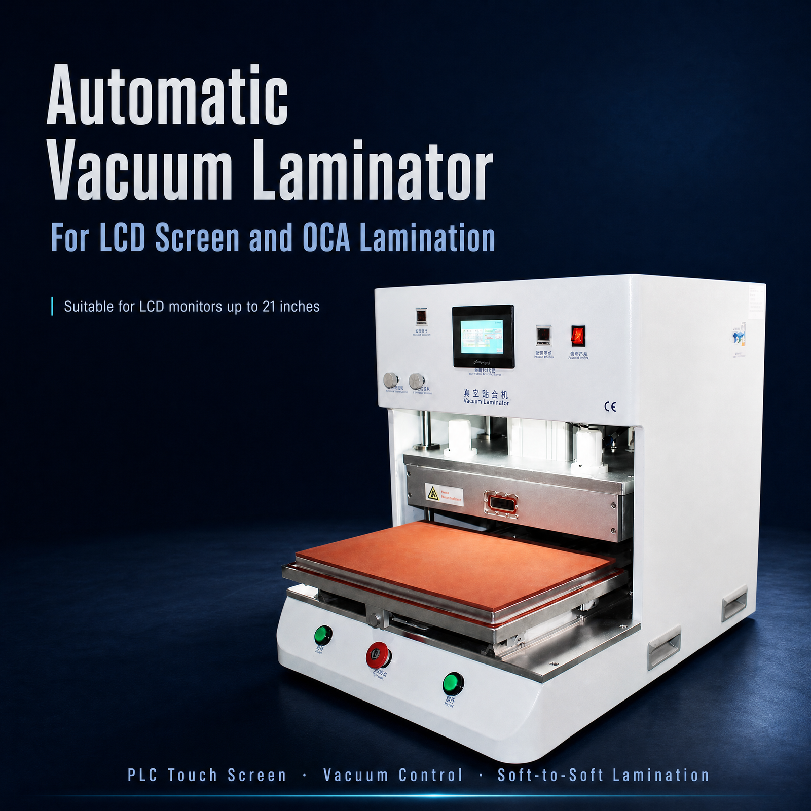
21-Inch OCA Vacuum Laminating Machine
This single-station configuration is relevant when the complete assembly remains within a 450 × 300 mm fitting area. Its product page lists applications including industrial display panels, HMI screens, in-vehicle display modules and touch-panel assemblies.
For smaller panels: operations that can keep the full display, tooling and handling allowance inside the confirmed fitting area.
View 450 × 300 mm Machine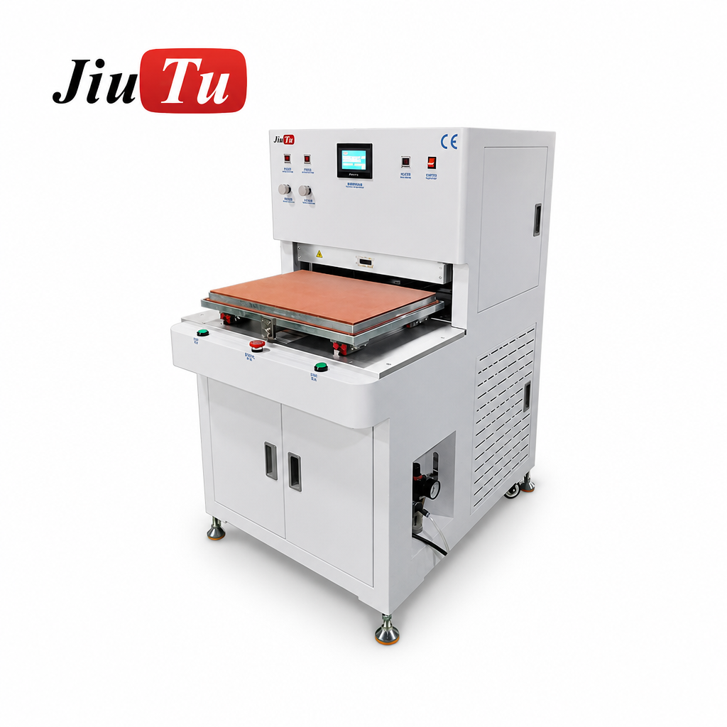
550 × 380 mm Vacuum Laminating Machine
The product documentation defines 550 × 380 mm as the working-platform area and states that the panel assembly plus fixture must fit inside that envelope. Listed applications include LCD full lamination, industrial HMI assembly, in-vehicle display modules and digital-signage panel bonding.
Where the limit matters: this platform can suit a workshop’s regular fixtures. If a required envelope is wider than 550 mm, even by a small amount, this configuration should not be assumed to fit.
View 550 × 380 mm Machine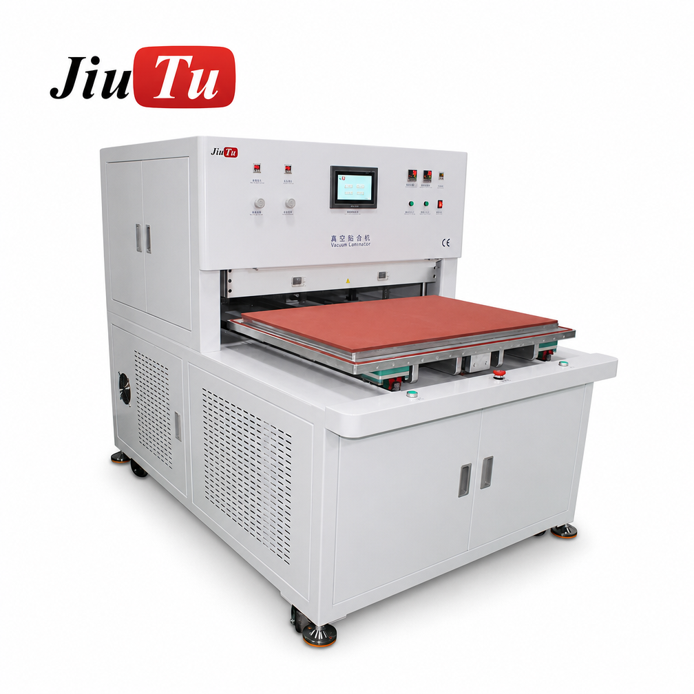
500 × 700 mm Vacuum Laminating Machine
Here the platform itself is specified as the working area, with the panel required to remain within the envelope after fixture clearance is considered. The product page covers large LCD full lamination, digital signage, large industrial HMI and wide-format display applications.
When extra length helps: a panel-and-fixture package that exceeds the smaller class may fit here once both axes and the loading orientation are verified.
View 500 × 700 mm Machine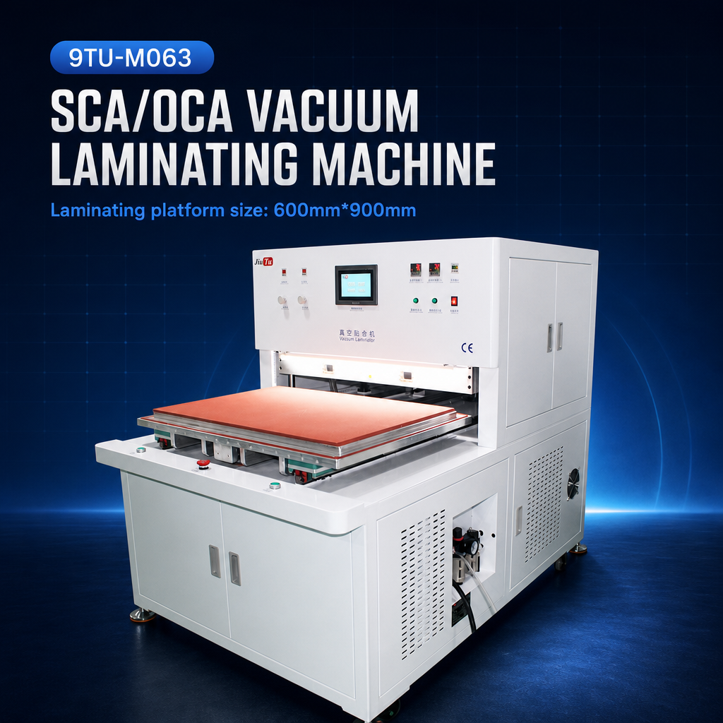
600 × 900 mm Vacuum Laminating Machine
JiuTu specifies the 600 × 900 mm dimension as the working-platform area and explicitly requires the panel plus fixture to remain inside that envelope. The machine page identifies large LCD/LCM, digital-signage, industrial HMI and wide-format display bonding among its intended application groups.
For recurring wide-format work: operations with large-panel or wide-format tooling requirements that justify this platform size after confirming the usable process area.
View 600 × 900 mm Machine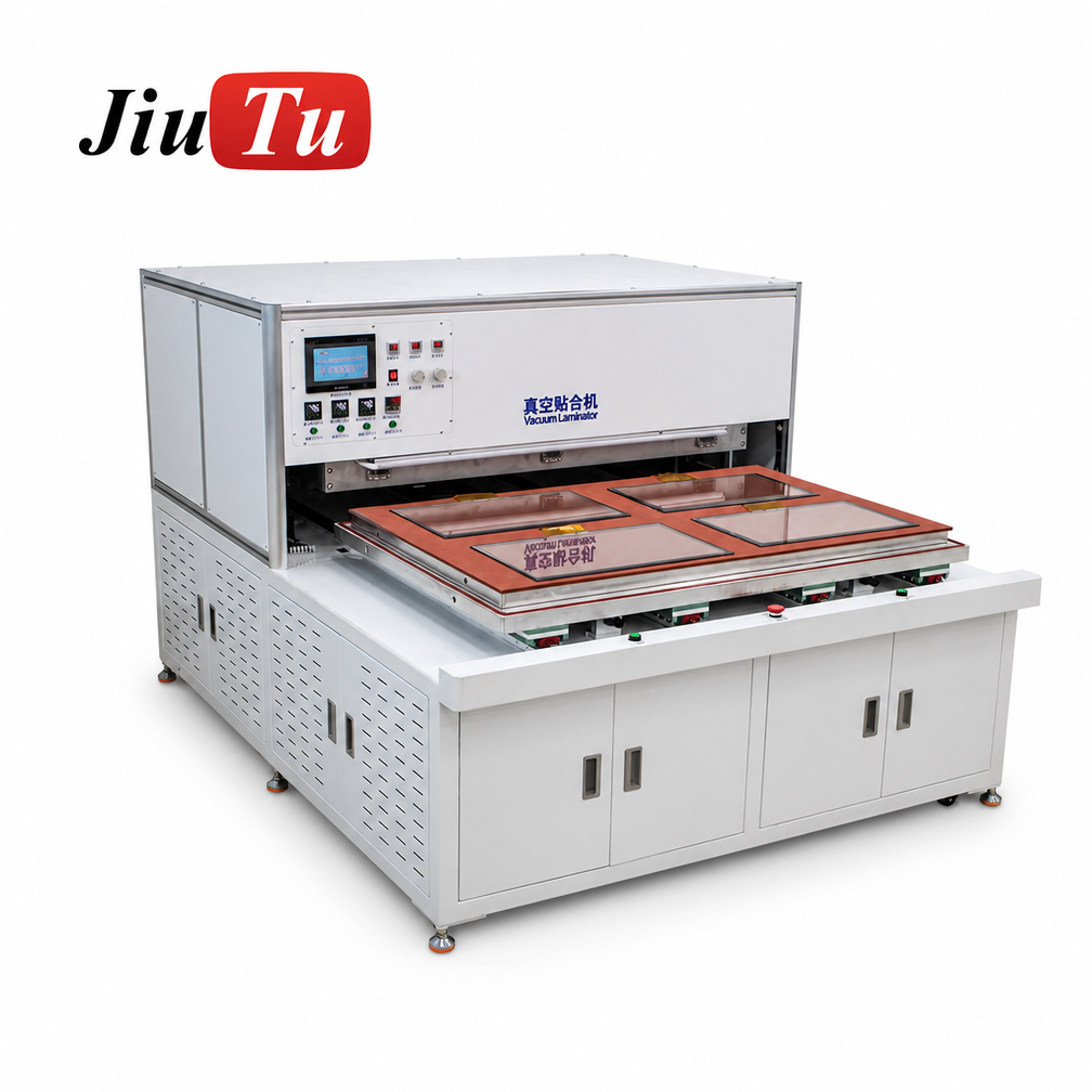
850 × 1350 mm Large-Format Vacuum Laminating Machine
This is the extra-large working-area direction in the current bonding-machine range. Its product documentation states that panels plus fixture must fit within the 850 × 1350 mm working-platform envelope and lists applications such as large LCD full lamination, digital signage, public information displays and wide-format industrial panel assemblies.
When the extra-large area is justified: factories whose measured large-panel or batch fixture needs this footprint—not simply buyers seeking the largest available machine for possible future work.
View 850 × 1350 mm MachineUse the product dimensions as comparison boundaries, not automatic purchase recommendations. The next step is to overlay the real fixture drawing on the proposed working area and confirm tooling, panel geometry, access, process compatibility and utilities for that configuration. To review the complete range together, see the OCA vacuum laminating machine collection.
Check the Largest Panel and Everyday Workload
A machine should pass two sizing tests before the purchasing team treats the selection as technically mature. One case tests whether an occasional oversized order is possible; the other tests whether the same platform makes sense on an ordinary production day.
Case A · Maximum workpiece
Can the largest planned assembly really fit?
- Largest panel or cover-glass outline
- Complete production fixture boundary
- Actual loading orientation
- Required handling and alignment clearance
- Loading opening and fixture-height constraints
- Required bond area within the approved process region
Case B · Regular workload
Does the platform fit everyday production?
- Most frequently processed panel family
- Regular production fixture and changeovers
- Typical single-panel or batch arrangement
- Operator access and changeover practicality
- Defined future panel sizes, not speculative growth
- Utility and floor-space implications of a larger class
A shop may handle one unusually large panel each month and much smaller work on most days. The largest fixture sets a hard size limit, but the regular mix affects loading, changeovers and how much platform is used. That trade-off is a stronger basis for choosing a size class than purchasing extra area for an undefined future order.
Prepare a drawing that purchasing, engineering and the supplier can all interpret
The drawing should show the panel orientation, cover-glass outline, fixture boundary and required clearance on the same top view. Label X and Y clearly. If another tooling set changes the outside dimensions, send it as a separate case rather than combining several products into one vague “maximum screen size.”
What to send for a configuration review
A supplier can give a more meaningful answer when the enquiry describes the actual assembly and workload. A screen diagonal alone leaves too many dimensions unresolved.
- Maximum LCD/OLED module width and length
- Cover-glass outside dimensions
- OCA or other planned bonding material
- Fixture outside dimensions
- Dimensioned loading-orientation drawing
- Flat or curved panel information
- Single-panel or batch-loading arrangement
- Most common panel dimensions
- Expected output requirement
- Current process or defect requirement
- Available voltage and required utilities
- Destination and installation constraints
Request a written confirmation of the usable working area for the proposed configuration rather than relying only on the model name. When sample testing is needed, define the exact sample stack and fixture so the result relates to the product that will enter production.
Vacuum Laminator Sizing FAQs
Is panel size the same as the required laminator working area?
No. The panel is only one part of the production envelope. Cover glass, OCA placement, fixture dimensions, locating features and loading clearance can all increase the required width or length. Use the largest complete package that enters the bonding position.
How much clearance should be allowed for tooling and alignment?
There is no single clearance value that applies to every machine. The required allowance depends on fixture design, alignment method, loading direction and handling access. Define that requirement from the actual tooling and then ask the supplier to confirm the complete envelope against the usable area.
Can several small LCD panels be loaded in one cycle?
Potentially, but the full multi-panel arrangement should be treated as one batch envelope. All panels, fixtures and required spacing must fit within the confirmed working region. Cycle capacity, heating or pressure coverage and production results should be verified for that exact loading arrangement rather than estimated from platform area alone.
Should the largest machine be chosen to leave room for future panels?
Only when the future requirement is defined well enough to justify the additional working area. Compare the known future fixture envelope with the larger configuration and also consider installation space, utilities and the sizes processed most often. Unused capacity by itself is not evidence that a larger machine is the better production fit.
Can a panel fit the platen but still be unsuitable for lamination?
Yes. The platform may be large enough while the loading opening, fixture height, usable bonding region or required support arrangement remains unsuitable. A dimensional match is only the starting point; the supplier still needs to confirm the process and loading conditions for the actual stack.
Application & Purchasing Check
Final Checks Before Choosing a Laminator
Choosing the right vacuum laminator working area for LCD panels comes down to two practical questions: will the largest assembly fit and bond correctly, and will the machine suit the work that runs most often? A dimensioned fixture drawing gives the manufacturer something concrete to check against the usable process area and loading path.
If those two cases point toward different machine sizes, explain the trade-off when requesting a configuration review. This is more useful than choosing the largest platform simply because it leaves theoretical room to grow.
- Largest combined panel-and-fixture envelope fits on both axes
- Everyday single-panel or batch setup remains practical
- Loading orientation is agreed for the real fixture
- Handling clearance reflects the actual loading method
- Curved-panel support is reviewed where applicable
- Loading opening and fixture height are checked
- Usable bonding region is confirmed by the supplier
- Utilities, installation route and sample testing are agreed as needed