
A panel can fit inside a laminating machine and still be a poor fit for its fixture. The trouble often lies underneath the display: a connector sits where the fixture supports the panel, a locating edge has moved, or the assembly cannot be loaded without catching on something. That does not always mean buying a new jig. Custom display bonding tooling becomes worth considering when standard or adjustable support cannot solve the problem reliably.
When a Panel Fits but the Fixture Does Not
Imagine adding a new display module to a lamination line that already handles a similar size. The platform has room for it. From above, the existing fixture looks suitable. Only after the full module is placed on the support do the differences become obvious.
Perhaps the flexible connector extends below the module, or the underside has a step that the older panel did not. Even a familiar outer shape can be misleading if the edge used for locating the previous model is no longer a reliable reference.
The question is not whether the new panel fits once, but whether it sits where it should every time. If the fixture supports the intended surfaces, avoids sensitive features and locates the assembly consistently, there may be no reason to replace it. If an operator must tilt, shift or manually correct the panel to make it work, that is a stronger sign the support needs attention.
Machine size can create a false sense of security here. A platform may accommodate the panel itself but not the carrier, fixture height or movement needed to load it. The usable working space matters more than the panel dimensions alone.
When comparing OCA vacuum laminating machines, it helps to look at the display stack, fixture footprint and pressing clearance together. A machine that accepts the panel on paper still has to accept the complete setup in practice.
The Details That Make Custom Tooling Necessary
An irregular outline does not, by itself, justify a dedicated fixture. What matters is where the assembly touches the support, what the tooling uses as a reference and whether anything gets in the way during loading or pressing.
Take a cover-glass assembly with a touch sensor and display module beneath it. Those layers do not always share the same outline or thickness. A fixture designed around the visible glass can end up resting against a connector or raised feature underneath rather than the support area intended by the design.
That small contact point matters because it changes how the assembly carries the applied load. The fixture may appear stable while placing force through a component that was never meant to support it.
Positioning can fail more quietly. The easiest edge to push against is not necessarily the right datum. If the stops follow a cosmetic edge or a perimeter that varies between models, repeated loading can produce different locations even though the fixture itself has not moved.
And a clearance check made only after the panel is seated can miss the real problem. A connector may catch as the module is lowered into place, or the combined height of carrier and display may interfere with the press. These are reasons to reconsider the fixture geometry—not merely to choose a larger platform.
The useful distinction is therefore between a different-looking panel and a genuinely different support requirement. Only the second one points clearly toward new tooling.
Our guide to fixture design for flat, curved and irregular displays goes deeper into geometry. Here, the more immediate question is whether a change to the existing fixture can do the job, or whether the support concept itself must be different.
The locating reference should also make sense for the process used to align the layers. The discussion of alignment methods for optical film application explains why mechanical location and optical alignment need to work together.
What actually warrants a new fixture? A support point, datum or clearance requirement the existing arrangement cannot meet reliably—not just another screen size.
When an Adjustable Fixture Is Enough
For a family of related displays, adjustable tooling may be all that is needed. The dimensions or locating positions can change while the areas that support the assembly—and the features that must stay clear—remain much the same.
Repositionable stops or interchangeable support pieces can then accommodate several models without a completely different jig for each one. That is useful only if the settings can be restored consistently between changeovers.
But moving a stop cannot fix a support surface that presses against a connector. Nor will adjustment alone solve an altered load path or insufficient clearance beneath the assembly. Those problems may require a different contact arrangement, not a wider adjustment range.
Consider three related modules built around the same support zones. One adjustable jig could be practical across all three. If a fourth model moves a connector directly into one of those zones, forcing it onto the shared setup creates a different problem; a dedicated support may be easier to use and validate.
Production frequency changes the calculation. A shared jig that needs several adjustments and checks at every changeover may not save much time on a high-volume line. For an occasional variant, though, the extra cost and storage of a dedicated fixture may be harder to justify.
The choice is usually straightforward once the real constraint is clear: keep the standard fixture if it locates and supports the assembly correctly; use an adjustable one if only dimensions or stop positions change; consider dedicated tooling when the contact arrangement changes or setup repeatability suffers.
Before You Ask for a Tooling Quote
A request for custom tooling can go in circles when it starts with only the panel’s length and width. A complete assembly drawing is far more useful: it shows the stack, overall thickness, relevant tolerances and the connectors or raised features that may affect support.
Mark the permitted contact areas and no-contact zones on the same drawing. With a clear locating datum, there is less room for disagreement about how the panel should sit in the fixture. An easily accessible outer edge should not be assumed to be the correct reference.
The process belongs in that conversation too. Loading direction, available height and the intended pressing sequence can change what the fixture needs to accommodate. Where relevant, share the actual temperature, pressure, holding-time and vacuum requirements from the process specification and material documentation rather than estimating them for the quote.
If several models will use the same equipment, include drawings for representative variants. Differences that look small in a product list may be significant at the support points—and vice versa.
That is also the right moment to consider the machine, rather than treating the fixture as a separate purchase. JiuTu has two relevant configurations that illustrate how platform space and pressing control change the discussion.
Where the equipment choice matters
The same display may call for a different setup depending on the available space and how force is applied.
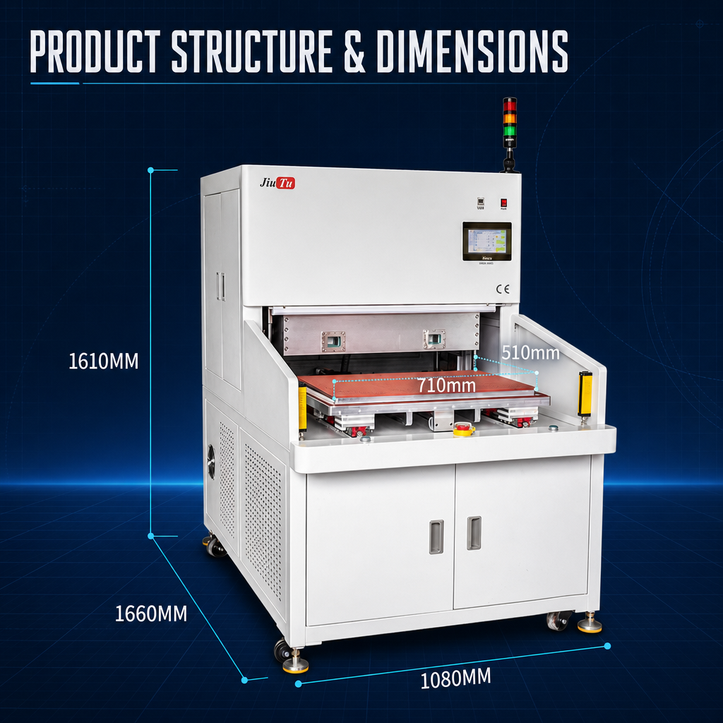
The marked working platform helps put fixture footprint into perspective.
Fixture space and staged pressing
9TU-M040D Industrial Vacuum Laminating Machine
With a 710 × 510 mm working platform and 85 mm lamination height, the 9TU-M040D gives a useful starting point for assessing the footprint and height of a fixture-assisted setup.
Its staged pneumatic pressing and recipe settings are relevant when the bonding process calls for defined pressing stages. The important measurement is the space occupied by the complete display-and-fixture combination, not just the glass.
The proposed fixture and representative stack should be reviewed together before the configuration is finalized.
Review the 9TU-M040D configuration →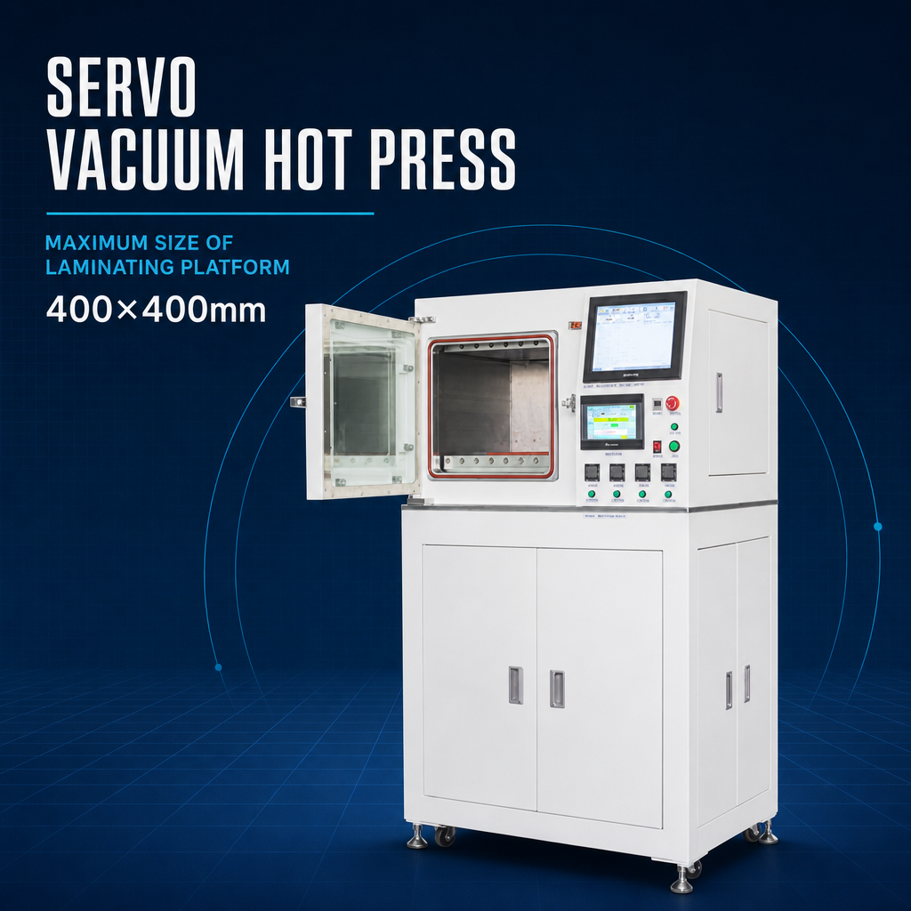
The standard 400 × 400 mm platform is one part of the fixture-space check.
Servo pressing and platform configuration
400×400-2T Servo Laminating Machine
The 400×400-2T starts with a 400 × 400 mm platform. Its platform configuration can be discussed against the intended workpiece and tooling.
What makes this machine a different option is its servo-controlled pressing, with pressure and displacement modes. It becomes relevant when control of pressing force or final position is as important as the fixture footprint.
As with the pneumatic option, the actual display stack and tooling design determine whether it is a suitable fit.
Explore servo machine specifications →The choice is less about which machine is more capable in general and more about the constraint that matters for this display. The 9TU-M040D brings a larger published platform and staged pneumatic pressing; the 400×400-2T offers servo-controlled pressure or displacement. Neither removes the need for a well-matched fixture.
Once the assembly drawing, usable working space and pressing process are clear, a tooling quote can address the actual challenge instead of relying on assumptions that may surface after the fixture is made.
The Real Test Is on the Production Floor
A fixture that looks convincing in CAD can still be awkward at the machine. The first meaningful trial is with a complete display assembly or representative sample, not an empty fixture or a nominal panel outline.
Watch how the operator places and removes the assembly. Does it settle naturally onto its support surfaces and locating references, or does a connector, flexible circuit or another sensitive feature get in the way? A part that is clear when seated may still catch on the way in or out.
Then repeat the loading. If the datum is difficult to find, the operator may make small corrections that are easy to miss in a single demonstration. For a shared fixture, try changing models and returning to the original setup; the adjustment must be repeatable, not merely possible.
The bonding cycle is the other half of the test. Unexpected movement, contact or visible deformation under the intended process conditions suggests a problem that a static fit check could not reveal.
Record what was actually tested: the display and fixture revisions, loading orientation, machine configuration and validated process conditions. That detail matters when the next display revision arrives. A good result for one stack should not silently become approval for another.
A practical sign that the fixture is ready: the assembly moves through loading, alignment, bonding and removal without unexpected contact or constant hand correction.
When a shared fixture cannot return to its original setting reliably, the adjustment method may need revisiting—or the frequently used model may be better served by its own jig.
Frequently Asked Questions
Can adjustable tooling replace a dedicated fixture?
Often, yes. If the models share the same support zones and locating references, adjustable stops or support elements may be enough. A different contact surface or clearance requirement is a stronger reason for a dedicated jig.
Who should approve the support drawing?
Mechanical or process engineers should confirm the support areas, datum and clearances. Quality can agree on acceptance criteria, while production verifies that loading and model changeover work in practice.
Does a new display size always need new tooling?
No. Size alone is not the deciding factor. If the assembly still has reliable support, positioning and clearance with the existing fixture, a new jig may add little value.
Planning a bonding setup?
Choose Tooling That Fits the Display—and the Process
If you are unsure whether your display needs a new fixture, share the assembly drawing and a few details about the intended bonding process. Layer thickness, connector locations, permitted support areas and available machine space will help JiuTu discuss whether standard, adjustable or dedicated tooling is the sensible next step.