
Visual acceptance after optical bonding is not a microscope-based pass-or-fail check. It is an agreement about how the finished display should look, under which viewing conditions, and how the location and appearance of a defect affect the decision. In practice, reliable criteria combine consistent viewing conditions, location-specific limits and representative reference samples. Closer inspection can help explain a questionable feature, but it should not quietly change the agreed acceptance threshold. Electrical, optical-performance and reliability checks remain separate.
Why a Bonded Display Needs Its Own Acceptance Boundary
After optical bonding, quality teams are no longer judging a display panel in isolation. They are looking at an assembly that brings together the cover glass, adhesive layer, display panel and visible transitions between them. A feature that is easy to overlook in one area may be distracting in another, so a general instruction to check for a clean appearance leaves too much room for interpretation.
Visual acceptance is also only one part of final quality release. A display can look uniform and still require electrical or functional verification. The reverse is equally possible: a panel may operate correctly while a visible mark falls outside the customer’s cosmetic requirements. Treating appearance and performance as separate decisions prevents one inspection result from being used as proof of the other.
Timing matters, too. A quick check immediately after bonding can reveal obvious process issues, but it is not necessarily the same as final acceptance after bubble removal or other downstream processing. The assembly may be in a different condition, and the purpose of the check has changed. Where both stages matter, they need distinct acceptance expectations. This article focuses on the finished assembly and its post-bonding visual release, rather than an earlier in-process go/no-go decision.
A useful visual standard leads to a clear disposition—accept, rework, hold for review or reject—and gives the team enough context to understand why. It should also fit the wider production sequence. Cleaning, alignment, bonding, bubble removal and final QC are connected stages, so a finding is more useful when it can be related to the point at which it first appeared. For that broader process context, see the display bonding workflow.
Only after the inspection task is clear does equipment selection become relevant. JiuTu’s laboratory precision instruments range is worth reviewing when closer observation or image documentation is needed, but the inspection method—not the available magnification—should determine the equipment choice.
Why the Same Bonded Display Can Look Different
A visible feature does not appear independently of its surroundings. A faint scratch, particle or optical variation may be easy to see under one light source and difficult to distinguish under another. Viewing distance, observation angle and display state can change the result as well. If a manufacturer and customer inspect the same panel under different conditions, both may feel their judgment is reasonable while still reaching different conclusions.
Distance and angle change what the eye notices
At the normal inspection position, a small mark may not attract attention. Move closer or tilt the cover glass, however, and reflections or surface details can become more prominent. That closer view can help identify a feature, but it should not automatically replace the agreed viewing position used for routine acceptance.
The distinction is important: routine viewing answers whether the finished display meets its agreed appearance requirement in its intended inspection context; magnified examination helps investigate what a questionable feature actually is. If magnification is part of the acceptance method, it should be agreed in advance rather than introduced only after a disagreement occurs.
Lighting and display state reveal different features
Diffuse illumination gives a broad view of the surface, while directional light can make scratches, particles and some edge irregularities easier to notice. Neither setup is automatically the right one for every display. The choice depends on the product’s intended use and the defects the inspection is meant to reveal. Any numerical illumination requirement should come from the applicable customer specification or a validated inspection method, not from an assumed industry-wide value.
The display’s operating state changes what can be assessed, too. An unpowered panel viewed under controlled external lighting is useful for examining surface conditions. A uniform test pattern can make certain optical non-uniformities easier to see. Orientation, ambient reflections and surface cleanliness also matter, particularly when inspection takes place at different facilities.
For a borderline finding, the most useful comparison is one made under the same agreed conditions. If a closer examination is needed, retain it as supporting evidence and keep it distinct from the routine acceptance view unless the approved method explicitly includes both.
A Defect Cannot Be Judged by Appearance Alone
Location can matter as much as the defect itself. A small bubble in the active viewing area may interrupt the image or draw the user’s attention; a similar feature near a concealed border may have a different impact. The same principle applies to particles, scratches and adhesive irregularities. Treating the entire cover glass as one inspection zone overlooks how the finished product is actually seen and used.
Most display assemblies need a distinction between the active viewing area, the border or transition around it, and non-viewing regions. These are working categories, not universal acceptance zones: their boundaries should follow the product drawing and the assembled construction. The transition area deserves particular attention because edge lift, incomplete bonding coverage or adhesive overflow may be relevant there even when the active image area appears unaffected.
Defect names are useful only when they describe something specific. A report that says “bonding defect” does not tell another reviewer what was found or where. The examples below show the kind of information that makes a finding comparable; the actual limits still need to come from the display specification and customer agreement.
| Defect category | What matters when reviewing it |
|---|---|
| Bubbles | Location, visible extent and distribution, particularly whether the feature falls within the active viewing area. |
| Particles | Whether the particle is on an accessible surface or within the bonded assembly, along with its position and visible appearance. |
| Scratches | Surface location, direction, extent and visibility under the agreed viewing conditions. |
| Stains or contamination | Affected area and appearance, including whether the condition changes after an approved cleaning procedure. |
| Wrinkles | Position, shape and affected region, especially where film or adhesive layers are involved. |
| Bonding-edge defects | Edge lift, incomplete coverage or adhesive overflow, including the affected length or area relative to the bonding boundary. |
These observations become acceptance criteria only when they are tied to a defined limit and outcome. For example, the agreement may need to specify the relevant zone, a measurable size or affected length where appropriate, the viewing condition and whether the result is accepted, reworked, held or rejected. A threshold suitable for one display construction should not be copied to another simply because the defect has the same name.
Written descriptions rarely settle every borderline case. A small reference set—with an approved sample, a rejected sample and, where useful, a borderline example—gives production teams and customers something concrete to compare. Each sample should be traceable to the defect, location and decision it represents. It should also reflect the actual construction: cover glass, adhesive, printed borders and layer arrangement can all affect how a feature appears.
Photographs help when physical samples cannot be shared between sites, but they are only useful comparisons when lighting, exposure, angle and magnification are controlled. Otherwise, the image may introduce another source of disagreement. The aim is not to build a large image library; it is to preserve a small, representative set that makes the agreed visual boundary understandable.
What Makes an Acceptance Decision Defensible?
Even a well-defined visual standard becomes difficult to apply consistently if the inspection evidence is not traceable. When a question comes back weeks later—or when another site reviews the same issue—the team needs to reconstruct which assembly was checked, under what conditions, against which reference and who approved the result.
That does not require an elaborate report for every panel. The record should connect the display model and revision, relevant lot information, viewing setup, defect location and category, reference-sample ID, supporting image or measurement, and final disposition. The level of detail can reflect the inspection process, but the decision should never depend on an undocumented verbal judgment.
Images are especially useful when a feature is difficult to describe. A photograph tied to the product revision, location and inspection conditions gives another reviewer a basis for comparison. If a measurement is included, its method and calibration status should be recorded. A value shown on a microscope screen is not automatically a formal dimensional result unless the method has been validated for that purpose.
Where closer observation helps
Routine visual inspection and detailed defect investigation do not always call for the same equipment. Magnified observation is useful when a team needs to locate a particle, examine a bonding edge, compare a borderline feature or capture an image for review. It is less useful when the underlying problem is that the acceptance conditions have not been agreed in the first place.
For closer examination of display-module features, JiuTu lists the SI-VMA Automatic Focusing Video Microscope for OLED, TFT, LCM and LCD applications. Its relevance to a particular bonded assembly depends on the sample dimensions, working distance, field of view, illumination response and the feature being investigated—not magnification alone.
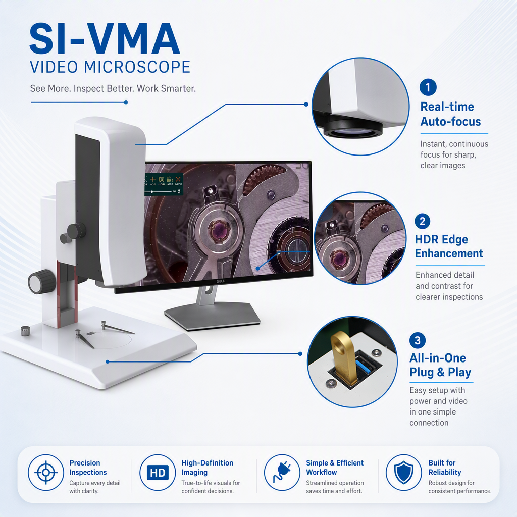
Display inspection candidate
SI-VMA Automatic Focusing Video Microscope
A video microscope option for examining selected display-module features and retaining supporting visual records.
- Automatic, one-touch and manual focus modes
- 1080p HDMI output; external monitor required and not included
- Adjustable LED ring illumination
- On-screen measurement and image documentation functions
Confirm the observation range and sample configuration before deciding whether it suits the inspection task.
View SI-VMA Product DetailsThe microscope can make a feature easier to examine and document; it cannot decide whether that feature is acceptable. That decision remains tied to the agreed cosmetic specification. Teams comparing display inspection equipment should therefore start with the observation task and evidence required, while keeping electrical and reliability testing within their own verification processes.
When Two Inspectors Reach Different Conclusions
Most disagreements begin before anyone discusses the defect limit. One inspector may have used directional light, another diffuse illumination; one may have viewed the panel at the agreed distance, while another moved closer or changed the angle. The display may also have been in a different operating state. Unless those conditions are aligned, comparing the two judgments is unlikely to resolve the issue.
The first step is to return to the agreed routine viewing conditions and confirm that the sample has not been cleaned, handled or altered since the original observation. The finding can then be compared with the defect map and the nearest approved or borderline reference sample. A magnified image may help explain what the feature is, but it should support—not silently replace—the original acceptance view.
If the existing examples do not cover the condition, the assembly should remain on hold until an authorized quality representative reviews the evidence. The team should not create a new rejection threshold at the inspection bench. If the decision changes the acceptance rule, the controlled specification and reference samples need to be updated so that later production is judged against the same interpretation.
Repeated disagreements can also reveal a weakness in the inspection setup. If inspectors cannot distinguish accepted and borderline samples under the agreed conditions, the method may need clarification before a different instrument is considered. For a configuration discussion, the most useful starting information is the display stack, representative defect images and the viewing conditions the team needs to reproduce.
Frequently Asked Questions
Can a microscope define the acceptance threshold by itself?
No. A microscope helps identify and document a feature. The acceptance threshold still comes from the agreed product specification, viewing conditions, defect zones and reference samples.
Should functional testing be separate from visual inspection?
Yes. Visual inspection addresses appearance. Electrical operation, touch response, optical performance and reliability need their own applicable verification methods.
What if the specification does not cover a particular defect?
Keep the affected assembly on hold, document the observation and obtain a decision from the authorized quality representatives. If the interpretation becomes a new acceptance rule, add it to the controlled specification and reference samples.
Display Inspection · Configuration Review
Match the Inspection Setup to the Display Application
A useful equipment discussion starts with the display construction and the features the quality team needs to examine. Once the viewing conditions and acceptance method are clear, an observation system can be assessed against the actual task.
If you are reviewing a microscope for a bonded display, the following details will help establish whether a configuration is suitable:
- Display dimensions and bonded layer structure
- Typical defect types and representative images
- Agreed viewing distance, angle and illumination
- Required working distance and observation range
- Image capture or measurement requirements
Share the display stack and a few representative defect images to discuss whether the SI-VMA microscope or another inspection configuration is appropriate. Final suitability should be confirmed against the sample and inspection method.