
A dependable HDMI microscope workstation is built in a fixed sequence: establish the sample and stand geometry, connect the HDMI signal and approved accessories, set the field of view, tune illumination before exposure, verify color and focus on a representative sample, then save a repeatable baseline. The goal is not simply to obtain a large picture on a monitor. A production-ready station should let different operators return to a comparable inspection view without rebuilding the setup each time. For the SI-VMA, the external monitor is not included and must be planned as a separate workstation component.
- 01 Sample Real board or part
- 02 Stand Height and clearance
- 03 Lighting Angle and intensity
- 04 Camera Focus and exposure
- 05 HDMI Stable signal path
- 06 Monitor Inspect and record
Start With the Workstation, Not the Magnification Setting
The first setup decision should be based on the actual PCB, PCBA, connector, display module, machined part or inspection fixture. A microscope that produces a sharp image can still be awkward in daily use if the stand cannot clear a tall component, the board cannot rotate beneath the lens, or the monitor forces the operator to keep turning away from the sample.
Place a representative part on the intended bench before finalizing the stand position. Check the total sample height, fixture height, expected hand movement and any tools that must enter the working area. A bare PCB and a populated board with tall capacitors or connectors can require very different clearance even when the same defect is being inspected.
The useful workstation is the relationship between sample access, microscope position and screen location—not any one component by itself.
Monitor size should be selected for the viewing distance and inspection task rather than simply choosing the largest available display. A large screen can make fine defects easier to discuss with a team, but it also requires enough bench depth and appropriate placement. For general display ergonomics, the OSHA workstation monitor guidance recommends positioning the primary display directly in front of the user at a comfortable viewing distance, with the top of the screen at or slightly below eye level.
Confirm the quotation scope before installation. The SI-VMA uses an external display for large-screen inspection, but the monitor is not included. Treat the monitor, microscope, stand, illumination, sample support, USB devices and recording method as separate workstation items that need to be confirmed.
This is also the right point to create the first strong commercial link in the buying path. If the application requires direct large-screen PCB or component inspection, review the HDMI microscope setup around the SI-VMA together with the monitor and sample-handling requirements rather than evaluating the camera body alone.
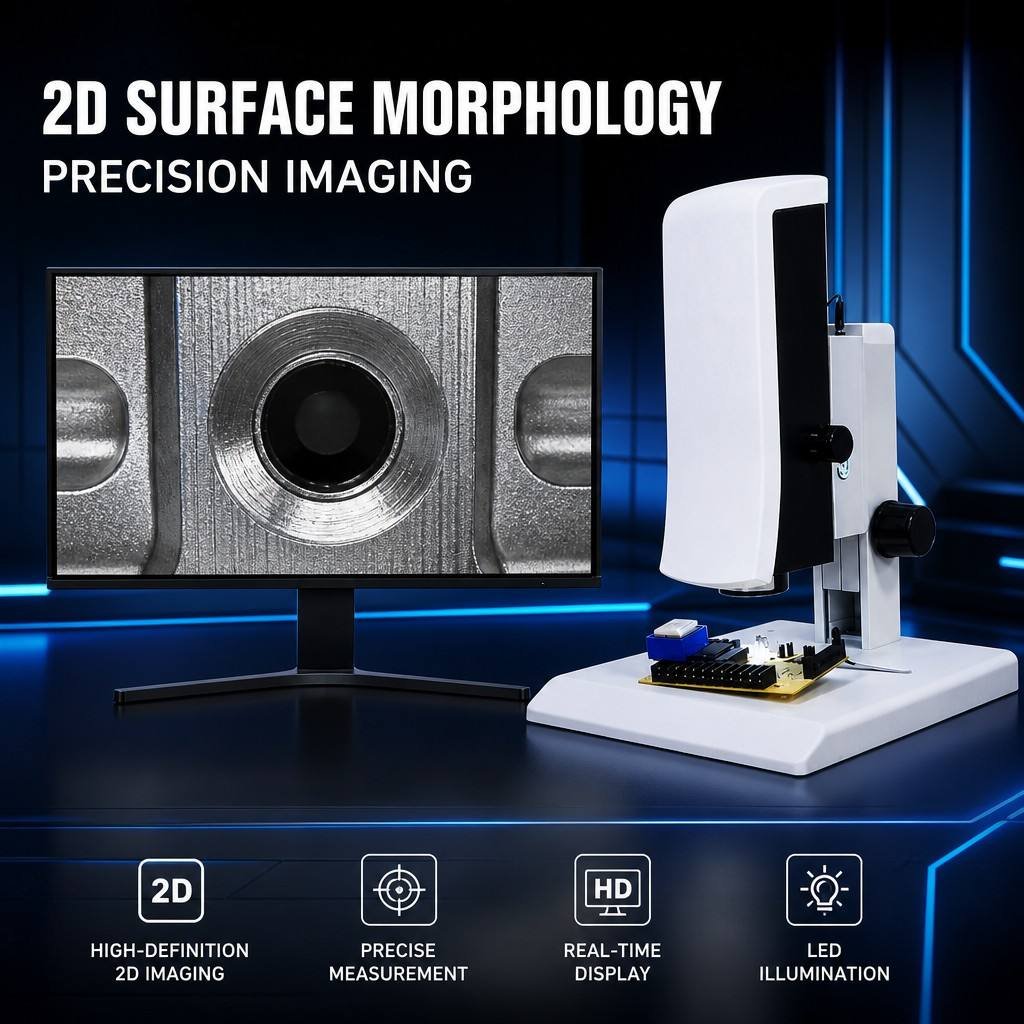
Connect the HDMI Signal and Accessories Before Fine Optical Adjustment
Once the physical arrangement is acceptable, build the signal path while the workstation is still easy to access. The SI-VMA provides 1080P HDMI output for direct monitor viewing. Start with the simplest path—microscope to monitor—before adding any other equipment between them. Splitters, converters or capture devices should only be introduced after the direct connection has been proven stable.
Seat the cable firmly at both ends and note which monitor input is being used. This prevents a later “no signal” diagnosis from starting with the wrong source selected on the display.
The SI-VMA interface is mouse-driven, and USB storage can be used for captured files. Test the devices that will actually stay at the workstation rather than qualifying the system with temporary accessories.
Leave enough service slack for normal movement, but do not allow a cable loop to catch a fixture or pull the microscope when an operator moves a sample.
If the screen reports no signal, check power, the selected HDMI input, connector seating and the cable before changing focus, lighting or image controls.
Cable management is part of image stability. A stand can appear to “lose focus” when the real problem is a cable pulling the microscope body slightly as the sample is moved. The same is true when a board tray catches a power lead. A stable signal path and a stable mechanical path should be established together.
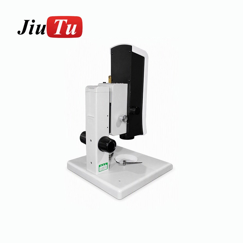
Where the SI-VMA fits naturally
Large-Screen Visual Inspection Without a PC-Centered Workstation
The SI-VMA is a logical fit when the primary job is to inspect surfaces, components, solder joints, traces, edges or other visible defects on an external monitor. The system combines autofocus operation, HDMI viewing, on-screen controls and direct USB file handling in one inspection workflow.
- PCB and PCBA quality inspection
- Incoming component or connector checks
- Electronics assembly and process inspection
- Laboratory or engineering defect review
- Shared viewing when several people need to discuss the same feature
Set Geometry First, Then Lighting, Then Camera Controls
A common setup error is to start changing exposure or digital settings while the mechanical viewing condition is still moving. Build the image from the sample upward. The stand height and working clearance define what the optics see; lighting defines what surface information reaches the camera; exposure and white balance then refine that image.
Use the actual fixture or representative board. Leave enough room for rotation, probing or hand movement if those actions belong to the process.
An operator still needs context. If only one pad fills the screen, it may become harder to relocate the same region on the next board or compare a defect with surrounding joints.
The SI-VMA provides Auto, One-Touch and Manual focus modes. A production team can choose the method that gives the right balance between repeated automatic correction and deliberate control over the focal plane.
The correct setting depends on whether the sample is matte, reflective, dark, light or mixed. The same intensity will not be ideal for every PCB surface.
The SI-VMA provides exposure and white-balance controls through the on-screen interface. Use them to stabilize the approved view rather than compensate for a poor lighting angle.
Reflective solder joints need lighting control before exposure correction
Solder joints, metal shields and polished connector surfaces can create specular reflections. On a large monitor, those reflections may appear as featureless white areas even though the surrounding board looks correctly exposed. Lowering overall exposure can make the rest of the image too dark without restoring useful information inside the highlight.
See whether the highlight starts to show surface structure or edge detail.
Where the setup permits it, alter the sample orientation or lighting relationship so the strongest reflection moves away from the feature being judged.
Once the illumination is useful, use exposure to place the complete scene within a readable brightness range.
The SI-VMA also provides HDR and edge-enhancement functions for difficult surfaces. These can be useful when bright and dark regions must be inspected in the same field, but they should not replace correct lighting. An image-processing tool works on the information captured by the camera; it cannot recover a feature that was completely hidden by poor geometry or saturation.
Qualify the Station With a Reference Sample Before Routine Use
A visually impressive demo image is not an acceptance test. Use a reference sample that represents the inspection work the station will perform. For PCB quality control, that sample might contain fine silkscreen, IC leads, solder joints, traces, connector contacts, a board edge and surfaces with different reflectivity.
The reference sample should make small setup changes visible. If the only test feature is a large printed logo, a slightly soft image may still look acceptable. Fine component edges and low-contrast details give operators a much stronger basis for determining whether the workstation has returned to the approved condition.
Confirm that known fine features are clearly resolved in the normal working area without relying on excessive digital enlargement.
Move the reference feature toward the practical edge of the field and confirm that inspection remains useful without constant recentering.
Check a known board under the approved illumination so unexpected white-balance changes are easier to recognize after restart.
Remove and replace the sample several times. A fixture stop, orientation mark or board reference can be more valuable than additional magnification when the same region must be inspected repeatedly.
Ask another trained operator to reproduce the inspection view from the written setup condition. This exposes undocumented adjustments that only the first operator knows.
If measurement is part of the inspection, visual sharpness alone is not sufficient. The SI-VMA includes on-screen measurement tools and calibration functions, so the measurement workflow should be calibrated for the intended viewing condition according to the supplied operating instructions. A scale that is correct at one calibrated condition should not simply be assumed to remain valid after a change that affects the measurement relationship.
Separate visual acceptance from dimensional acceptance. “The image looks sharp” answers a visual-inspection question. “The measured value is valid” requires a controlled measurement method, calibration and a reference appropriate to the required dimensional decision.
Diagnose the Workstation by Symptom Instead of Changing Everything at Once
When a large-screen microscope image does not look right, change one variable at a time. A simultaneous change to stand height, lighting, exposure and monitor controls may improve the picture, but it destroys the information needed to understand the original cause or reproduce the correction later.
Check power, the monitor’s selected HDMI input, connector seating and the HDMI cable. Test a known-good direct cable before introducing a splitter, converter or capture device.
Check first: power → input → cable → direct connection.
Determine whether the visible flicker comes from the display, the illumination or the camera image. The SI-VMA includes an anti-flicker control, but the correct response depends on identifying the source rather than switching settings at random.
Check first: monitor → lighting → anti-flicker setting → local power environment.
Return to the reference sample and verify the stand, sample height and focus method. A larger monitor makes small focus errors easier to notice; it does not create optical detail that was not captured.
Check first: reference sample → mechanical stability → focus → field of view.
Change lighting intensity or geometry before making a large exposure correction. The objective is to preserve detail on the reflective feature without pushing the rest of the board into an unnecessarily dark image.
Check first: light intensity → reflection angle → exposure → HDR if needed.
Check whether the lens housing, a tall component, fixture or operator’s hand is blocking the illumination. Increasing brightness does not remove a geometric shadow.
Check first: obstruction → light position → sample orientation.
Inspect stand stability, bench vibration, cable pull and sample support. If touching the board shifts the complete field on the monitor, the solution belongs in the mechanical workstation before it belongs in the camera menu.
Check first: sample support → stand → cable routing → bench.
Saving an approved image of the reference sample can make troubleshooting faster. The SI-VMA can capture files to USB storage, so a team can keep a visual baseline alongside the written workstation settings. A saved image does not replace calibration or inspection criteria, but it gives operators a practical comparison when the current view suddenly appears different.
Know When an HDMI Microscope Is Enough—and When You Need a Measurement System
Not every inspection requirement should be solved by buying more magnification. The correct equipment depends on the decision the quality team needs to make. Large-screen visual inspection and automated dimensional metrology overlap in imaging, but they solve different problems.
For most PCB/PCBA visual inspection stations, the SI-VMA remains the more direct choice because the workflow centers on a live, magnified image and operator inspection. A much larger metrology system is unnecessary when the real requirement is simply to inspect solder joints, components, traces, particles or assembly defects efficiently on a monitor.
When the inspection requirement changes from “Can I see the defect clearly?” to “Can I repeatedly measure geometry, height, profile or tolerance across parts?”, the equipment decision changes as well.
When the requirement becomes dimensional
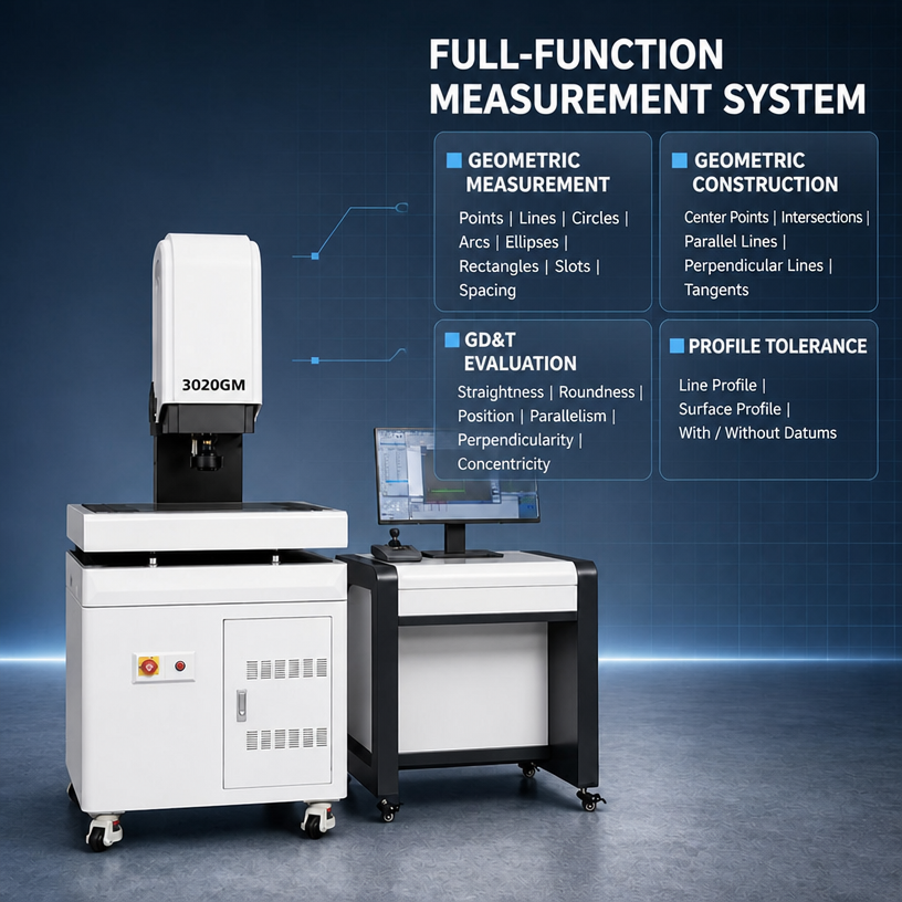
3020GM Three-Dimensional Composite Imaging Measuring Instrument
The 3020GM belongs in a different inspection tier. It combines optical imaging with 3D measurement functions for applications where the QC result needs dimensional data rather than only a magnified visual image.
That makes it relevant for teams evaluating part dimensions, position, flatness, profile or other controlled measurement tasks. It should not be treated as a more expensive substitute for every microscope workstation; it becomes useful when the inspection requirement itself has moved into dimensional metrology.
Who is the SI-VMA workstation a practical fit for?
The strongest fit is a team that needs repeatable large-screen visual inspection without building a PC-heavy imaging station around every bench. Typical users include PCB/PCBA quality teams, electronics factories, incoming inspection departments, laboratories, engineering teams and production areas that need several people to review the same defect on a monitor.
Autofocus is especially useful when inspected regions sit at different heights or operators move repeatedly between features. It reduces the amount of manual focus correction required, but it should be viewed as part of the workflow rather than as a substitute for a stable stand, correct lighting and sensible sample positioning.
What should procurement confirm before ordering?
Do not purchase the microscope as an isolated line item if the real objective is a working inspection station. Confirm the external monitor, stand arrangement, illumination, sample dimensions, typical sample height, required field of view, recording method, measurement requirement and operator workflow together.
For buyers who are not yet sure whether the job belongs to a video microscope or a more advanced measurement system, the site’s laboratory precision instruments section provides the relevant inspection equipment path without mixing the decision with unrelated lamination or autoclave equipment.
Frequently Asked Questions
Can any HDMI monitor be used with the SI-VMA?
The SI-VMA is designed for direct 1080P HDMI monitor output. In a straightforward microscope-to-monitor installation, use a standard HDMI display that accepts the required signal. If the workstation introduces converters, splitters or capture hardware, verify the complete signal path before production use.
Why does the microscope image flicker on a large screen?
Flicker can originate from the monitor, lighting source, local power environment or camera settings. Isolate the source first. The SI-VMA includes an anti-flicker function, but it should be used as part of diagnosis rather than as an automatic fix for every type of flicker.
How should lighting be adjusted for reflective solder joints?
Start with illumination rather than exposure. Reduce light intensity and change the reflection geometry until the joint retains visible edge or surface information. Then refine exposure and, where useful, evaluate HDR for scenes containing both bright and dark regions.
Does the SI-VMA include an external monitor?
No. The external monitor is not included. It should be specified separately according to the workstation’s HDMI connection, available bench space, operator viewing position and desired display size.
A successful HDMI microscope setup is not defined by how large the image looks on the first day. It is defined by whether the same sample can be positioned, illuminated, focused and reviewed consistently after the workstation is restarted, another operator takes over, or a different production part is placed under the microscope. Build the station around that repeatability and troubleshooting becomes easier, training becomes clearer, and equipment selection stays tied to the actual inspection requirement.
Application & Configuration Review
Send the Real Inspection Requirement Before Finalizing the Workstation
For a useful configuration review, describe the actual sample and inspection decision rather than asking only for a microscope price. The information below helps determine whether the application needs a large-screen video microscope workstation, additional accessories or a more measurement-oriented inspection system.
- PCB, panel or sample dimensions
- Maximum sample or component height
- Material and surface type
- Defect or process requirement
- Visual inspection or dimensional measurement
- Expected inspection volume
- Required image or data recording
- Voltage and destination
With these details defined, the next step can focus on the real workstation: microscope, display, stand, lighting, sample handling and documentation method—not simply one magnification figure.