
Bubbles after LCD lamination should be diagnosed before pressure, temperature or cycle time is changed. Start with three facts: where the defect appears, what it looks like and when it becomes visible. An edge bubble that is present immediately after lamination, a central void around a particle and a bubble that returns only after cooling are different troubleshooting cases. The practical sequence is to document the defect, check cleaning and material handling, verify alignment and lamination, review the vacuum stage, and only then decide whether the LCD/OCA bubble-removal process needs adjustment.
Edge, corner, center, around a visible point, or the same repeated zone.
Round void, narrow separation line, haze, irregular pocket, or particle-centered mark.
After lamination, after bubble removal, while warm, after cooling, or hours later.
Read the Bubble Pattern Before Touching the Settings
A final inspection tells you where the defect was noticed, but not necessarily where it was created. That distinction is important in OCA bonding because cleaning, adhesive handling, alignment, vacuum lamination and post-lamination bubble removal all affect the final appearance of the display.
Before running the next panel, photograph the defect under consistent lighting. For edge defects, add a side-light image because a thin separation line may be easier to identify when light passes across the bonded interface. Record whether the position repeats from one panel to another and whether the same tooling, operator, tray position or material batch is involved.
Repeated edge bubbles deserve an upstream check before a stronger cycle is attempted. Review perimeter cleanliness, OCA placement, cover-glass alignment, panel support and the visible result immediately after lamination.
Inspect first:
edge contact and alignment
A central void may be residual air, but first establish whether it was already present when the panel left the laminator. If it was, investigate vacuum lamination, support and contact before assuming the bubble-removal stage is underpowered.
Inspect first:
lamination and vacuum result
When a fixed point remains visible in the center of a void from different viewing angles, treat dust or another contaminant as a serious possibility. Pressure may reduce the visible air around it, but it cannot remove the particle.
Inspect first:
cleaning and contamination
If the panel looks clear after processing and the bubble reappears later, record exactly when the change occurs. The useful evidence is the difference between the immediate result and the cooled or later inspection result.
Inspect first:
material, wet-out and cycle history
If contamination, visible misalignment and material damage have already been ruled out, the next process question is whether the remaining defect is genuine residual air. That is the point where post-lamination LCD/OCA bubble-removal equipment becomes relevant. The category should be evaluated as a post-lamination process step, not as a universal fix for every bonding defect.
A repeated location is valuable evidence. If the same corner, border or central zone fails across several panels, look for the process condition that is also repeating: fixture position, support, alignment reference, cleaning zone, loading orientation or material handling method.
Trace the Problem in the Same Order the Panel Was Built
When the cause is uncertain, troubleshoot from upstream to downstream. This prevents the easiest machine setting from receiving attention before simpler physical causes have been eliminated.
Cleaning and the working environment
Inspect the surfaces that will be permanently enclosed by the bond. Look for dust, residue, fingerprints, fibers or other contamination before lamination. If the operation handles multiple panel families, also check whether trays, gloves, cleaning tools or static conditions change between products.
Diagnostic question: Is a solid particle physically preventing full contact?
Adhesive condition, storage and handling
Identify the exact adhesive being used and review its storage and handling history against the material supplier’s documentation. Do not compensate for uncertain material condition by simply raising downstream temperature or pressure.
Diagnostic question: Do the defective panels share the same adhesive lot or handling history?
Alignment, support and initial lamination
Check whether the display, OCA and cover layer are correctly positioned and supported during bonding. A display bubble-removal autoclave cannot move a shifted layer back into alignment. If the defect follows one fixture position or panel orientation, investigate that relationship before changing the later cycle.
Diagnostic question: Can the defect already be seen immediately after lamination?
Vacuum lamination stage
Confirm that the vacuum stage is performing consistently with the actual panel, adhesive, tooling and loading arrangement. The goal here is not to repeat the full lamination theory, but to establish whether air was already trapped before the panel reached the bubble-removal stage. For the upstream prevention mechanism, see how vacuum lamination prevents OCA bubbles.
Diagnostic question: Does the defect exist before post-lamination processing?
LCD/OCA bubble-removal cycle
Only after the earlier stages are satisfactory should pressure, temperature, time, process sequence and loading become the primary variables. The working recipe needs to be verified for the actual panel structure and adhesive instead of copied from another product family.
Diagnostic question: Does one controlled cycle change produce a repeatable improvement?
This upstream-to-downstream method also prevents a common diagnostic error: blaming the last machine in the workflow because that is where the defect was finally noticed. The defect may have been created several stages earlier.
Use Timing to Separate Immediate Bubbles From Bubbles That Return Later
When technicians ask why bubbles return after a display bubble-removal autoclave cycle, the most useful answer often comes from inspection timing. “There was a bubble after the cycle” is not specific enough. The panel should be compared at defined points.
If the bubble is already present here, investigate the lamination and vacuum stages first.
If the defect remains unchanged, confirm whether it is actually residual air rather than contamination or misalignment.
If the panel clears and then changes later, the delayed behavior becomes a separate variable that should be documented.
For delayed bubbles, do not judge the process only while the panel is still warm. Use the same cooling position, lighting and follow-up timing for comparison samples. If one panel is inspected immediately and another is inspected much later, the apparent process difference may actually be an inspection difference.
Delayed recurrence should also trigger a review of adhesive history and the original lamination quality. A downstream cycle can change the visible condition of a void without proving that the underlying bond is stable. The goal is a repeatable result after the defined inspection period, not simply a panel that looks clear at the moment the chamber opens.
For refurbishment centers processing mixed incoming models, create separate records by product family rather than treating every LCD or OLED assembly as equivalent. This prevents a validated result for one stack from becoming an assumed recipe for an unrelated display.
Change One Variable at a Time—and Know When to Stop Reprocessing
The most efficient troubleshooting process is often the least dramatic one. Start with a documented baseline, change one factor and keep everything else as consistent as possible.
This method is especially useful when a workshop has a high rework rate. If three variables are changed and the next batch improves, the team still does not know which adjustment mattered. That makes future failures harder to diagnose and can cause unnecessary process escalation.
Stop increasing heat or pressure when the evidence points upstream
- a fixed particle remains inside the defect;
- the cover glass, OCA, touch layer or display is visibly misaligned;
- surface contamination is suspected;
- adhesive condition or handling history is uncertain;
- the same defect repeatedly follows one fixture or lamination position;
- the applicable material or panel process limits have not been confirmed; or
- reprocessing introduces a new appearance or handling concern.
A panel should not be sent through repeated cycles simply because another cycle is available. If the defect belongs to contamination, material damage or alignment, the corrective action is not stronger bubble removal. Rework or rejection should follow the operation’s own acceptance criteria and the applicable material guidance.
When a Bubble Remover Is the Right Next Step, Match It to the Workload
Once the laminate is clean, correctly aligned and fundamentally sound, residual trapped air becomes a legitimate post-lamination problem. At that point, equipment selection should start with the complete loading envelope and workload—not with the largest pressure figure on a specification sheet.
A repair center handling mixed phones, tablets and moderate-size displays does not automatically need the same chamber format as a production line processing industrial TFT assemblies or large-format panels. The useful question is: what must fit, how will it be loaded, and how consistently does the process need to be repeated? Do not infer usable fit from a model name alone. Confirm the actual chamber opening and internal geometry, usable tray or shelf space, depth and fixture clearance for the exact configuration being quoted.
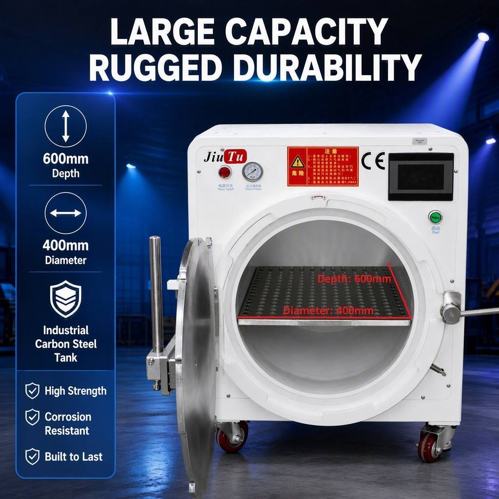
Mixed repair and refurbishment workflow
400×600mm OCA Bubble Remover Machine
This format is worth considering when the operation has moved beyond very small phone-only work but does not need a very large industrial chamber. Confirm how the current 400×600 designation maps to the usable chamber geometry on the exact machine configuration, then check the complete panel-plus-fixture loading envelope rather than relying on diagonal screen size alone.
Suitable for: refurbishment centers, mixed-model repair operations and teams that need more usable chamber space while keeping the workflow relatively compact.
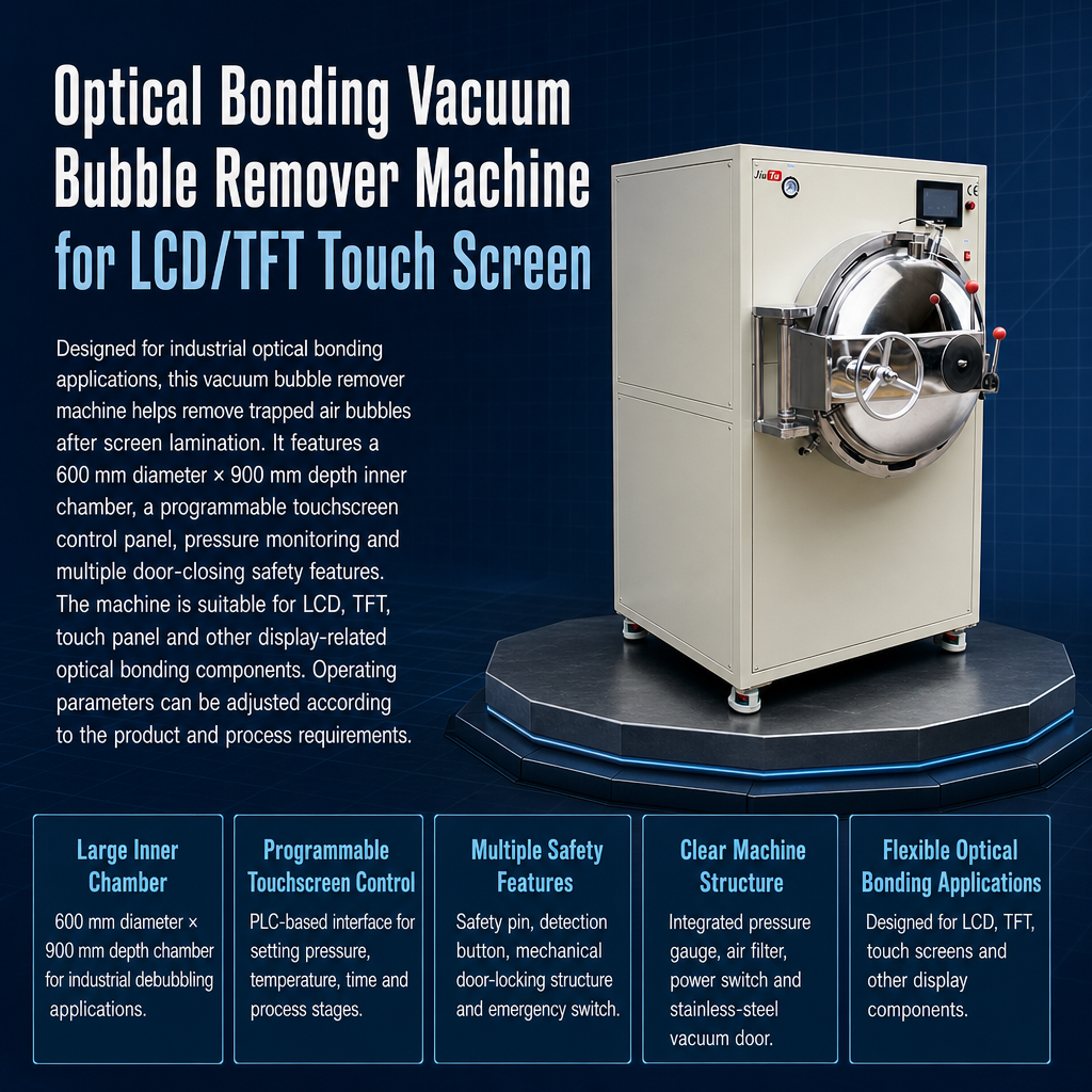
Industrial and repeated batch workflow
600×900mm Stainless Steel Optical Bonding Vacuum Bubble Remover Machine
This is a more relevant direction when the work involves larger optical-bonded assemblies, repeated batches or production environments where loading consistency and process control matter more than a small workshop footprint. Before purchase, confirm the clear chamber opening, internal loading space, tray or shelf arrangement and fixture clearance for the exact 600×900 configuration.
Suitable for: display production engineers, industrial screen operations, TFT and touch-panel workflows, and teams evaluating a dedicated larger-format post-lamination station.
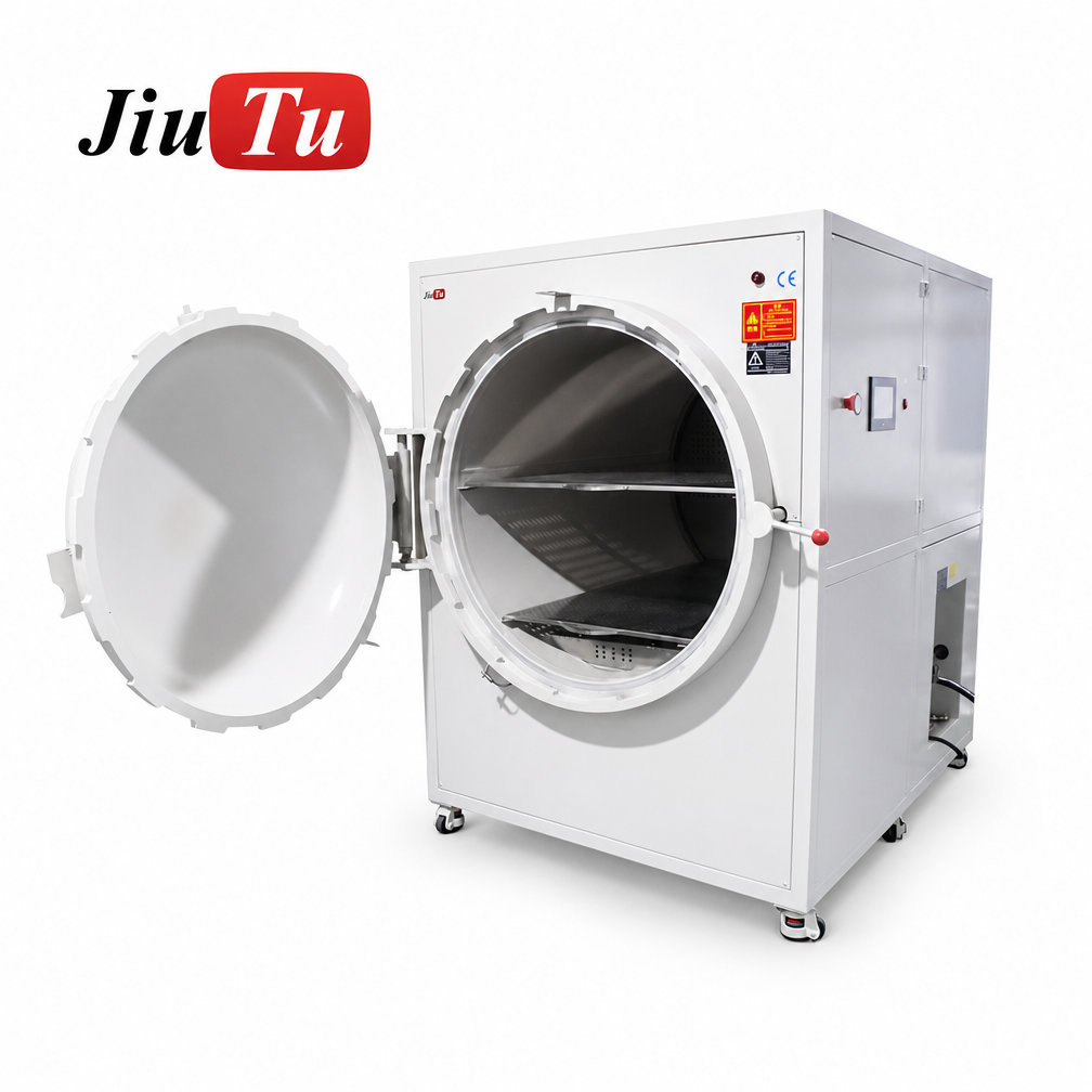
Large-panel workflow
800×1200 Carbon Steel Vacuum Bubble Remover Machine
When large display assemblies drive the requirement, chamber geometry becomes a purchasing issue rather than a secondary specification. The panel and any loading fixture must fit through the clear opening and within the usable internal loading space, while the tray or shelf layout must still support the intended production process.
Suitable for: large-format display work, industrial panels and operations where the maximum regular assembly—not the smallest product in the mix—should determine the equipment size.
These examples are not a ranking. A larger chamber is not automatically a better purchase. If most regular work is smaller, unused chamber capacity may add cost and floor-space requirements without improving the actual process. Conversely, a compact machine that cannot accept the largest regular panel or fixture creates an immediate production constraint. Compare the supplier-confirmed usable loading geometry, not only the nominal model size.
For a broader comparison of current chamber formats, controls and sizes, review the full LCD/OCA bubble removal equipment category after you have defined the real panel dimensions and workload.
What to Confirm Before Buying—or Before Asking a Supplier to Diagnose the Problem
A useful equipment recommendation requires more than “I have bubbles.” The same information that improves troubleshooting also improves purchasing decisions because it tells the supplier what the machine actually needs to process.
Send these application details
- maximum assembled panel width, height and thickness, plus the fixture or tray envelope;
- LCD, OLED, TFT, touch panel or other display structure;
- OCA or other optical bonding material identification;
- clear defect photos under front and side lighting;
- where the bubbles appear and when they become visible;
- current cleaning, lamination and vacuum process;
- current bubble-removal process, if one is already used;
- realistic daily output or batch requirement;
- available voltage and relevant utilities; and
- destination and installation requirements.
Ask these purchasing questions
- Does the clear chamber opening and usable internal loading space fit the largest regular panel plus fixture?
- What tray or shelf clearances remain after the panel and fixture are loaded?
- How will panels be supported and loaded consistently?
- Can the process be recorded or repeated by product family?
- Is the proposed capacity based on your real panel size?
- What utilities must be prepared before installation?
- Which configuration items need to be confirmed before the order?
- Can representative samples be evaluated before final configuration?
For operations with a high rework rate, repeatability deserves more weight than nominal chamber size alone. A machine should fit the maximum regular panel and fixture within its supplier-confirmed usable loading geometry, but the loading arrangement and process control also need to support a consistent production routine. Otherwise, each batch introduces another uncontrolled variable.
Representative sample validation is particularly useful when the panel structure, adhesive or defect is unfamiliar. It helps answer two questions before purchase: whether the bubble-removal stage actually addresses the defect, and whether the proposed chamber and loading arrangement fit the real application.
By the end of a disciplined investigation, bubbles after LCD lamination should no longer be treated as one generic problem. The defect should have been narrowed to contamination, material condition, alignment, lamination, vacuum performance or genuine residual-air removal. That classification tells the operation what to fix and whether new equipment is actually the next step.
Frequently Asked Questions
Why do bubbles appear again after cooling?
A bubble that appears only after cooling should be treated as a timing clue. Record whether the panel was clear immediately after processing, how long the defect took to return and whether the same behavior repeats. Then compare adhesive history, initial lamination quality, loading and the verified cycle before deciding that more heat or pressure is required.
Can dust look like an OCA bubble?
Yes. A particle can hold the bonded layers apart and create a visible void around itself. Inspect the area under different lighting angles or suitable magnification and look for a fixed point at the center. If contamination is already sealed inside the stack, a bubble-removal cycle cannot remove the solid particle.
Should pressure or temperature be increased first?
Neither should be increased automatically. First verify cleanliness, adhesive condition, alignment, lamination and the vacuum stage. If the LCD/OCA bubble-removal cycle is confirmed as the variable to investigate, change one process factor at a time within the limits validated for the actual material, panel and equipment.
When should a panel be rejected instead of reprocessed?
Do not keep reprocessing a panel when the observed defect is something the bubble-removal stage cannot correct, such as sealed particle contamination, visible layer misalignment or damaged material. The final decision should follow the operation’s acceptance criteria and the relevant adhesive or process guidance.
Next Step
Fix the Cause First. Size the Equipment Second.
If inspection confirms that the laminate is clean, aligned and fundamentally sound but residual air remains, compare LCD/OCA display bubble-removal machines by supplier-confirmed usable chamber geometry, loading arrangement and the needs of the verified application.
If the root cause or machine size is still uncertain, send the panel dimensions, material, defect photos, current process, output target, voltage and destination so the configuration discussion can start from the real application rather than a generic machine recommendation.