
The practical answer
For electronics inspection, a video microscope usually deserves priority when the workflow depends on shared viewing, screen-based defect review and documented evidence. A stereo microscope can be the better architecture when natural depth perception and continuous hand-tool coordination are central to the task. In a video microscope vs stereo microscope decision, the useful question is not simply which microscope reaches the larger magnification number. It is whether operators mainly need to inspect, communicate and record what they see, or inspect while continuously positioning tweezers, probes, components and soldering tools in three-dimensional space.
Scope of this comparison: “Video microscope” here means a camera-based system where the operator primarily works from a live display, while “stereo microscope” means a system where direct binocular stereo viewing is the primary observation method. Camera-equipped stereo microscopes and other hybrid or 3D digital systems can combine features of both categories, so they should be evaluated by their actual viewing and workflow architecture rather than by the product label alone.
What Actually Changes Between Video and Stereo Microscope Architecture?
The first difference is not magnification. It is how the operator receives the image. A conventional stereo microscope uses two optical paths to present slightly different views to the left and right eyes. The operator therefore receives direct binocular depth information that can help with judging the relative position of component bodies, solder, leads and tool tips.
A video microscope uses a camera-based imaging path and presents the live image on a display. A conventional single-camera setup should be treated as a two-dimensional displayed view rather than as a direct replacement for binocular stereopsis. Operators can still interpret geometry from focus, shadows, motion and familiar component shapes, but those visual cues are not identical to stereo viewing.
Video architecture
Strong when the image must be seen beyond one operator
- The live image can be displayed on a monitor for inspection, discussion and training.
- A correctly arranged screen-based workstation can allow the operator to look forward instead of remaining fixed to eyepieces.
- Capture, recording and measurement functions may fit naturally into the inspection workflow when the specific system supports them.
- Several people can discuss the same displayed defect without taking turns at an eyepiece.
Stereo architecture
Strong when the hands continuously work in three-dimensional space
- Two optical views provide natural stereoscopic depth cues.
- Tool height and relative position can be judged directly while working under the optics.
- The architecture is well suited to prolonged component manipulation, probing and detailed manual rework.
- Photo or video documentation depends on the actual microscope configuration and any camera hardware fitted to it.
Operator posture also deserves more careful treatment than “monitor good, eyepiece bad.” Screen viewing can support a more upright position only when the monitor is placed at a suitable height, distance and viewing direction. A monitor mounted too far to the side can simply replace forward bending with repeated neck rotation. A stereo microscope can also be comfortable when eyepiece height, stand position, chair and bench are configured around the operator.
Judge the complete workstation rather than the microscope alone. Test the microscope with the real bench, chair, fixture and expected inspection duration. An arrangement that feels acceptable during a short demonstration may behave differently during repeated production inspection.
Shared viewing becomes a more decisive distinction when a defect frequently moves from operator to quality engineer to supervisor. A monitor lets those people refer to the same displayed feature at the same time. That can reduce ambiguity during defect escalation and training because the discussion is centered on one common image.
When shared screen inspection is already part of the requirement, evaluating a video microscope against representative PCB or PCBA samples is more useful than comparing microscope types only by headline magnification.
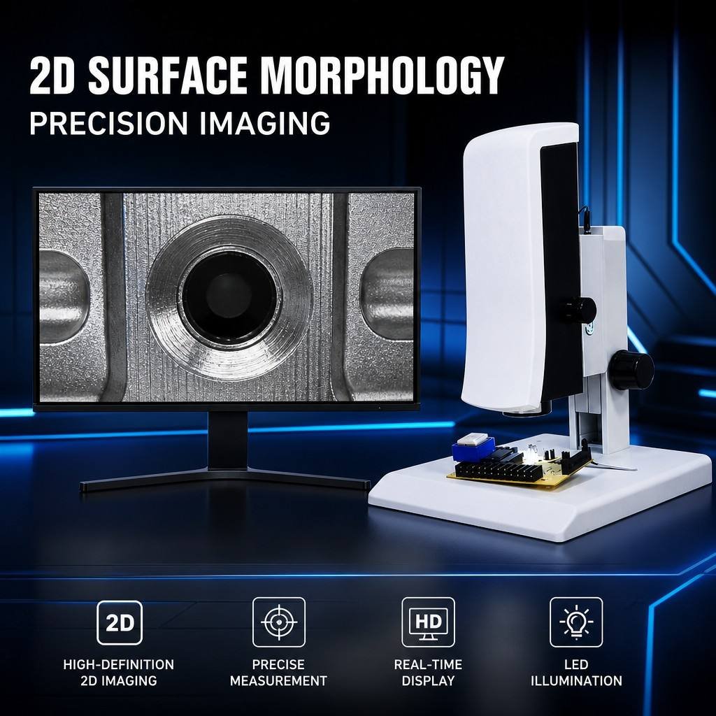
Depth Perception, Working Distance and Tool Access Matter More During Rework
The balance changes when visual inspection becomes physical rework. A technician may need to approach a fine lead with a soldering iron, position a small component with tweezers, touch a probe to a test point or move a tool around a tall connector without contacting adjacent parts. These tasks combine inspection with continuous hand movement.
This is where stereo depth perception can become particularly useful. The operator receives direct spatial cues while the tool moves through the work area. For a station dominated by detailed manual soldering or component placement, that visual relationship can matter more than shared viewing or digital capture.
Depth perception should not be confused with depth of field. Depth perception describes the operator’s ability to interpret three-dimensional spatial relationships. Depth of field describes how much of the scene in front of and behind the focused plane appears acceptably sharp. Depth of field depends on the optical setup and viewing condition and should be evaluated on the actual microscope rather than inferred from the words “video” or “stereo.”
Working distance is another separate decision variable. For electronics work, the useful clearance is not simply the space needed to fit a PCB below the optics. The station may also need room for a board fixture, tweezers, probes, a soldering iron, hot-air tools or both of the operator’s hands.
- Tool clearance
- Place the board in the real fixture and bring the largest regularly used tool into the work area. Verify that the microscope head, lighting, stand and fixture do not block the required approach angle.
- Hand-eye coordination
- Ask the technician to position the actual probe, tweezers or soldering tool while using the intended viewing method. Do not assume that a task comfortable through stereo optics will feel identical on a flat display. For video setups, confirm that live-image response and motion remain comfortable during the real hand movement required by the task.
- Useful field of view
- Check whether enough surrounding PCB context remains visible to identify the correct pad, lead or component while still resolving the defect or feature that matters.
- Operator posture
- Confirm that the viewing direction and hand position remain practical during a realistic work period, not only during a brief sample demonstration.
Before choosing a microscope for rework, test these physical conditions
A video microscope can still be suitable for solder joint inspection and for some rework operations. The important condition is that the operator can perform the required manipulation accurately and comfortably from the displayed image while maintaining enough working space around the PCB.
For PCB solder inspection, it is useful to separate visual inspection from active rework. If the station mainly checks solder quality and communicates defects, screen-based inspection can be highly practical. If the station spends most of its time actively soldering, placing and probing, stereo depth cues may deserve more weight.
When to choose a stereo microscope for rework: give stereo architecture more weight when operators continuously position tools in three-dimensional space and direct depth cues make that work easier. Give video architecture more weight when inspection, defect review and documentation dominate, provided any required rework has been tested successfully on the screen-based setup.
Photo, Video, Measurement and Shared Review Can Change the Inspection Workflow
Many electronics inspection tasks do not end when one operator notices an abnormal solder joint or component. The condition may need to be shown to a line leader, manufacturing engineer, supplier quality engineer or another inspector. A team may also need a before-and-after image, a short video, a dimensional check or a record that can be retained with the quality decision.
This is where a digital microscope vs stereo microscope comparison becomes operational rather than purely optical. A conventional stereo microscope is primarily a direct-view instrument unless an appropriate camera system is added. A video microscope already works around a displayed image, so capture and review functions can integrate more naturally when they are available on the specific system.
Locate the suspect solder joint, component, trace or surface feature.
Save visual evidence if the system supports the required image or video format.
Use the microscope’s measurement workflow when dimensional information is actually required.
Let QC, engineering or production discuss the same displayed condition.
Move the verified evidence into the factory’s normal quality documentation process.
When shared defect review is a frequent requirement, a monitor-based architecture has a straightforward advantage: several people can view the same live image at the same time. This can help with operator training, cross-functional defect discussion and incoming-quality decisions where a visual condition must be communicated consistently.
The exact documentation capability still has to be checked model by model. The term “digital microscope” alone does not prove that a system can save video, perform measurement, export data or integrate with a particular factory reporting process.
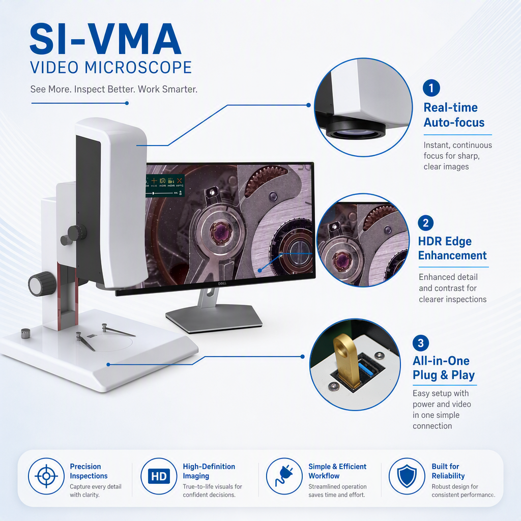
For the SI-VMA specifically, the confirmed inspection workflow includes HDMI display output, direct photo capture in JPG or BMP format, MP4 video recording, on-screen measurement tools and CSV measurement-data export to USB storage. These functions are operated through the microscope’s on-screen interface without requiring separate PC software for the microscope controls.
Verified SI-VMA functions relevant to electronics inspection
Those functions can support evidence collection, but they should not be confused with a complete factory quality-reporting platform or with a defined metrology capability. If measurements will be used for acceptance decisions, confirm the required calibration method, measurement accuracy and repeatability, zoom-specific calibration workflow, applicable traceability requirements and whether the system is suitable for the actual tolerance being checked. If the process requires a specific report template, automatic MES upload, serial-number traceability, approval routing or another software integration, that requirement should also be confirmed separately before equipment selection.
Which Microscope Makes More Sense for Four Common Electronics Workflows?
The same factory can reasonably use different microscope architectures at different stations. An incoming inspection bench, a line-side QC station and a dedicated rework bench may inspect similar components while requiring very different ways of working. The architecture should follow the task that occupies most of the station’s time.
Screen viewing is useful when a questionable component, connector, solder condition or surface defect has to be reviewed with purchasing, engineering or supplier quality. Captured visual evidence can also make acceptance decisions easier to communicate. A stereo microscope can still be appropriate when inspection requires frequent physical manipulation of three-dimensional parts.
Video inspection becomes attractive when the normal sequence is inspect, show the defect, save evidence and obtain a second opinion. If the same station also performs substantial corrective work with hand tools, tool access and depth perception deserve more weight in the selection.
A displayed image lets an instructor, operator and quality engineer refer to the same feature at the same time. That makes screen-based inspection especially relevant for defect-recognition training, solder-joint discussion and review of recurring production issues.
Natural stereoscopic depth can be valuable when operators continuously place components, follow fine leads with soldering tools or move probes around raised parts. A video system can still be suitable when the actual operator is comfortable with screen-based hand-eye coordination and the station provides sufficient clearance.
A mixed microscope strategy can therefore be more rational than forcing every workstation to use the same architecture. A quality area may benefit from screen-based viewing for shared defect analysis while a dedicated rework station retains stereo optics for prolonged manual manipulation.
For industrial inspection procurement, it is easy to focus on camera specifications, magnification ranges or accessory lists while overlooking the sequence of actions that operators repeat all day. The architecture has to fit that sequence first.
Where the SI-VMA Fits This Comparison
The SI-VMA Automatic Focusing Video Microscope belongs on the video side of this decision. Its published applications include PCB, PCBA and FPC inspection for solder joints, components and traces, as well as incoming inspection, in-process inspection, surface inspection and defect analysis.
That makes it relevant where an industrial video microscope for electronics inspection is being considered specifically for screen-based QC, defect communication and documented inspection.
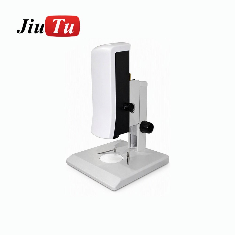
Consider the SI-VMA when the workflow is primarily screen-based
- PCB, PCBA or FPC inspection is part of the regular quality process.
- More than one person may need to review the same visible defect.
- Photos, video or measurement records are useful during inspection.
- An HDMI-connected external display fits the intended workstation.
- A standalone on-screen inspection interface is preferred.
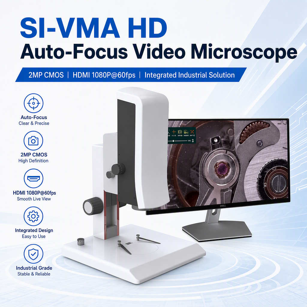
External monitor not included: the SI-VMA provides HDMI output for connection to an external display, but the monitor must be purchased separately.
The SI-VMA also provides automatic, one-touch and manual focusing modes. Those are confirmed product functions, but the decision between autofocus and manual-focus workflows is a separate equipment question. It should not replace the more fundamental architecture decision addressed here: screen-based video inspection versus direct stereo viewing.
If shared viewing, capture and screen-based PCB inspection match the actual requirement, review the SI-VMA inspection system against the sample types and defects that need to be verified.
Do not approve the microscope from magnification alone
A representative sample test is more useful than comparing the largest magnification numbers in two brochures. The test sample should contain the features and defect types that matter to the production decision. A clean demonstration board with large components may not reveal how the station behaves with reflective solder, fine-pitch leads, tall connectors, recessed features or a fixture that reduces tool access.
Run five checks with the real sample and workstation
- Verify defect visibility. Confirm that the actual solder joint, trace, component edge, contamination, scratch or other required feature can be recognized under realistic lighting and at a useful field of view.
- Verify working distance and tool access. Place the board in its normal fixture and bring the regular tweezers, probes or soldering tools into the work area. Do not evaluate clearance with an empty microscope stand.
- Verify operator posture. Position the chair, bench and monitor or eyepieces as they would be used during production. Check whether the operator can work without repeated leaning, twisting or reaching.
- Verify hand-eye coordination. If soldering, probing or component placement will be performed under the microscope, ask the actual operator to perform the task. For video systems, pay attention to live-image response and motion during fine hand movement rather than judging the setup from a static image. Do not assume that video and stereo viewing feel the same during fine manipulation.
- Verify the documentation workflow. Capture the image, video or measurement information the quality team actually intends to retain, then confirm how files will be named, reviewed and moved into the existing quality process.
This test can also reveal when an upgrade is unnecessary. A station used almost entirely for direct manual rework may gain little from capture functions that the team will never use. Conversely, an inspection station where supervisors repeatedly take turns at an eyepiece may benefit from shared screen viewing even before measurement features are considered.
The objective is not to prove that one microscope category is universally superior. It is to identify which architecture removes friction from the real process without creating a new problem in tool access, posture, coordination or documentation.
Frequently Asked Questions
Is a video microscope suitable for soldering and rework?
It can be, provided the workstation gives the technician enough working space and the operator can position tools accurately while watching the displayed image. For prolonged work where continuous three-dimensional tool positioning is central to the task, stereo depth perception may be preferable. Test the actual PCB, fixture and tools before standardizing the station.
When is stereo depth perception more important?
It becomes more important when an operator must continuously judge the relative height and position of tools and components, such as during component placement, fine probing or detailed soldering around raised parts. If the main task is visual inspection and defect communication, shared screen viewing may carry more weight.
Can multiple inspectors view a video microscope at once?
Yes. When the microscope displays its live image on an appropriately positioned external screen, several people can view the same image simultaneously. This can be useful for training, defect escalation and cross-functional review.
Is an external monitor included with the SI-VMA?
No. The SI-VMA outputs its image through HDMI, but an external monitor is not included and must be purchased separately.
Final selection logic
Choose the Architecture Around the Work, Then Validate It on the Real PCB
The most useful conclusion to a video microscope vs stereo microscope comparison is not that one technology replaces the other. Video architecture is generally the stronger candidate when shared viewing, defect evidence, measurement and documentation are central to electronics inspection. Stereo architecture deserves more weight when natural depth perception and sustained hands-on manipulation dominate the workstation.
Before ordering equipment, test representative samples for defect visibility, working distance, operator posture, tool access and the complete review or recording process. That exercise usually reveals more about practical suitability than a magnification-only comparison.
For a configuration review, provide the details that describe the real inspection application:
- Panel or sample dimensions
- PCB, PCBA, FPC or other material
- Smallest defect or feature to inspect
- Defect or process requirement
- Tools used and required working clearance
- Capture or measurement requirement
- Required measurement tolerance, if applicable
- Required voltage and installation destination