
Before confirming delivery for an industrial display bonding project, verify the selected machine’s electrical supply, external compressed-air requirements, floor capacity, installation clearance and delivery access. These details must match the actual model and configuration, not a generic equipment specification. Rated power alone does not establish the complete site electrical demand, and the machine footprint does not include operator or maintenance space.
For example, JiuTu’s 850×1350mm Vacuum Laminating Machine (9TU-M040) has published requirements of three-phase AC 380 V, 50 Hz and approximately 11.8 kW. Its published dimensions are 1,750 × 2,210 × 1,370 mm, with an approximate weight of 1,500 kg. These figures provide a useful planning reference for this particular candidate, not a standard for every laminator.
1. Confirm the Site Before Confirming Delivery
The first question is not simply whether a machine will fit inside the workshop. It is whether the selected configuration can be installed, connected, operated and maintained in the space available without creating problems for the surrounding production area.
Start with the actual display assembly. Its maximum width, height, thickness and weight matter, but so does the fixture used to position and support it. A panel that fits the nominal working platform may still be unsuitable if its alignment tooling, carrier or loading arrangement exceeds the available working envelope.
This is particularly relevant when comparing vacuum laminators with film laminating or other bonding equipment. Each machine performs a different task, so its working area, utility connections and installation requirements should be reviewed independently. The available display bonding equipment configurations provide a starting point for identifying the relevant equipment category.
It is also worth mapping the machine into the wider production layout. The loading position, unloading area, nearby inspection station, material storage and operator movement should be considered before fixing the final location. Where several process stations are involved, JiuTu’s guide to the complete display bonding workflow provides additional context for planning their relationship.
The practical decision: Approve the site only after the machine configuration, maximum workpiece, fixture arrangement, utilities and installation route have been considered together. A floor plan showing only the machine outline is not a complete installation plan.
2. Which Electrical and Air-Supply Details Are Model-Specific?
Electrical supply is one of the first items to verify because a facility’s available power may not match the machine’s specified connection. Having electricity available in the workshop does not necessarily mean that the correct voltage, phase, frequency or circuit capacity is available at the proposed installation point.
Electrical supply: rated power is only the starting point
The 9TU-M040 provides a useful example. Its published product information specifies three-phase AC 380 V, 50 Hz and approximately 11.8 kW. A facility with only a single-phase connection at the proposed location should not assume that the machine can be connected without an approved electrical configuration.
However, the 11.8 kW figure should not be treated as the complete site power calculation. Rated machine power and the electrical capacity needed to install the machine are related but different considerations. The facility assessment must also account for the actual current draw, starting characteristics, circuit protection, cable selection and other equipment that may operate simultaneously.
Request the manufacturer’s electrical documentation before arranging the connection. It should identify the rated supply, current information, allowable supply conditions, recommended protection, grounding requirements and connection point. The local electrical engineer can then determine whether the available distribution system and cable route are suitable.
Compressed air: establish whether an external connection is needed
JiuTu’s published 9TU-M040 documents identify a dry-air working source, but the pressure ranges are not fully consistent. The specification sheet lists 0.5–0.6 MPa, while the user manual lists 0.5–0.7 MPa. Both documents also state 4–6 kgf/cm² under “air supply pressure.” Before preparing the facility connection, ask JiuTu to confirm the applicable inlet pressure, required airflow and air connection details for the selected machine configuration.
For the 9TU-M040, the next step is to establish the final pneumatic connection requirements rather than assume that the published pressure values are sufficient for installation. Ask JiuTu to confirm the inlet location, acceptable operating pressure, continuous and peak air consumption, required air quality and any included filtration or regulation components.
A shared compressor may be suitable for several machines, but only when its available capacity and distribution network can support their combined demand. Pressure losses along the pipework and simultaneous operation should be included in that assessment.
Exhaust and ventilation need separate confirmation
Do not automatically add an exhaust duct to the facility plan simply because the equipment uses a vacuum system. Ask the manufacturer whether the selected machine has an external exhaust, cooling-air discharge or extraction requirement, and obtain the relevant connection details.
Room ventilation associated with process materials is a separate consideration. If adhesives or cleaning agents require particular handling conditions, review their supplier documentation and the facility’s applicable safety requirements rather than assuming that a machine exhaust connection addresses every ventilation need.
Electrical documentation
Confirm voltage, phase, frequency, rated power, current draw, starting characteristics, circuit protection, grounding and the actual connection location.
Pneumatic and exhaust documentation
Confirm whether external air or extraction is required. If applicable, obtain pressure, flow, air-quality and connection details before designing the facility supply.
These requirements should be documented for the exact machine configuration. If optional equipment or a customized arrangement changes the utility demand, the revised figures should be included in the final installation schedule.
3. What Space Is Needed Beyond the Footprint?
The machine footprint tells you how much floor area the equipment occupies. It does not tell you how much space is needed to load a display, position a fixture, open access panels or carry out maintenance.
The distinction is clear in the 850×1350mm Vacuum Laminating Machine. Its published working platform measures 850 × 1,350 mm, while the external machine dimensions are 1,750 × 2,210 × 1,370 mm. The complete panel and its alignment fixture must fit within the stated working platform area.
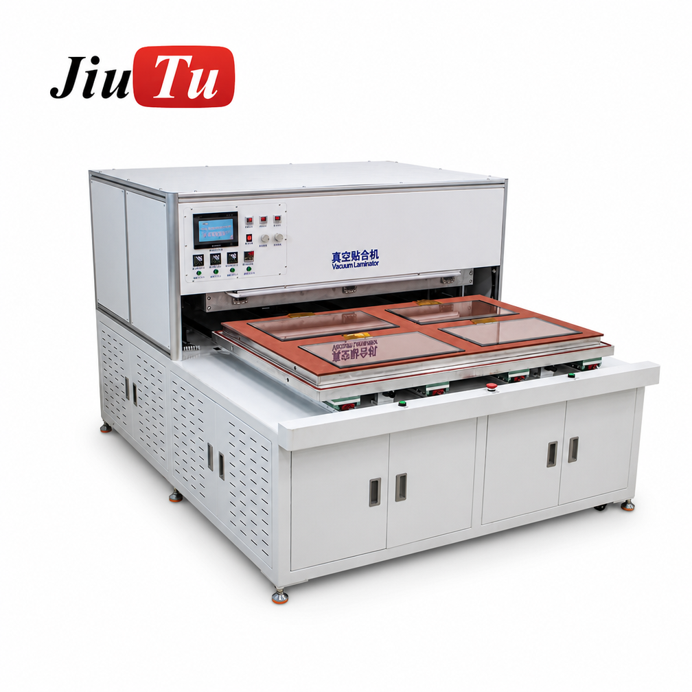
The published dimensions and weight provide a useful initial reference, but the facility should distinguish between the space occupied by the machine and the space required to use it.
| Published specification | What the site team should verify |
|---|---|
| Working platform 850 × 1,350 mm | Complete panel and fixture dimensions, loading orientation and usable working envelope. |
| Machine dimensions 1,750 × 2,210 × 1,370 mm | Final floor position, operator clearance, maintenance access and utility routing. |
| Approximate weight 1,500 kg | Floor capacity, support-point loading and handling arrangements. |
| Three-phase AC 380 V 50 Hz, approximately 11.8 kW | Available supply, circuit capacity, current requirements and electrical connection. |
Allow room for operation and maintenance
A large display assembly may need more room to handle than its dimensions suggest. Operators may need to approach the platform from a particular direction, align a carrier or move a heavy fixture without obstructing surrounding equipment.
Check the movement of platforms, doors and access covers under actual operating conditions. Maintenance access is equally important. Electrical cabinets, service panels and components requiring routine inspection should remain accessible after the machine has been positioned.
Utility connections also influence the final layout. Power cables, compressed-air lines and any required exhaust connections should have practical routes that do not obstruct walkways or prevent service access.

One additional point matters for specialized displays: a sufficiently large platform does not automatically establish fixture or curved-surface compatibility. If the application involves curved glass, unusual stack thicknesses or custom tooling, obtain written confirmation for the actual assembly and discuss sample validation before finalizing the equipment.
Considering the 850×1350mm configuration? Review the 850×1350mm Vacuum Laminating Machine and review equipment for your display project with the actual panel dimensions and fixture arrangement.
4. How Should Delivery Access and Floor Conditions Be Checked?
Installation planning should cover the entire route from the unloading point to the final machine position. A machine may fit comfortably in the production area but still be difficult to move through a narrow doorway, a corridor turn or an internal lift.
For the 9TU-M040, the published product information specifies an approximate machine weight of 1,500 kg and identifies forklift or crane positioning as necessary. Its 2,210 mm width is especially relevant when assessing access. However, the machine’s operating dimensions should not be confused with its packed shipping dimensions.
Request the final packing dimensions, gross shipping weight, lifting points and recommended handling arrangement. These details are necessary to determine whether the proposed forklift, crane, loading dock or internal transport route can handle the equipment safely.
Check the complete delivery route
Measure clear doorway widths and heights, corridor turning space, overhead obstructions, ramps and floor transitions. If an internal lift is involved, check its usable dimensions and rated load rather than relying on the building’s general passenger-lift capacity.
Also consider the space required by the handling equipment itself. A forklift may need additional turning room, while a crane arrangement may require a suitable lifting position and clear overhead access. The supplier and logistics team should agree on the handling method before dispatch.
Do not judge floor suitability by machine weight alone
The published 1,500 kg machine weight is a starting point for the structural assessment, not a floor-loading approval. The actual load transmitted to the floor depends on the support arrangement and the way the equipment distributes its weight.
Request the machine base dimensions, support-point locations and any available point-load or anchoring information. A qualified structural or facilities engineer should assess the proposed installation location, particularly for upper floors, mezzanines or structures with defined load restrictions.
The delivery route also needs review. Temporary loads from forklifts, cranes and transport equipment may differ from the final static machine load. Confirm that the route and unloading area can accommodate the planned handling operation.
What should be recorded before delivery approval?
Keep the annotated floor plan, doorway and corridor measurements, supplier packing details, lifting arrangement, floor-capacity confirmation and proposed utility connection locations together in the installation file.
Where floor leveling, vibration isolation or anchoring requirements apply, obtain the manufacturer’s installation instructions instead of using assumed industry-wide tolerances. These details should be settled before the machine reaches the facility.
5. Who Signs Off Site Readiness?
Site readiness is a shared responsibility. The equipment supplier understands the machine configuration, while the facility team understands the building, available utilities and local installation conditions. Both sides need to review the same technical information before delivery is approved.
Provides model-specific electrical and pneumatic information, machine dimensions, weight, installation drawings, packing details and lifting instructions.
Verifies voltage, phase, frequency, circuit capacity, cable routing, grounding and any required external utility connections.
Reviews floor capacity, support conditions, machine positioning, delivery access and the suitability of the proposed installation location.
Confirms the display stack, fixture arrangement, working envelope, operator access and actual production requirements.
Where applicable, the facility’s EHS or compliance personnel should also review ventilation, material handling and local installation requirements. These checks should be based on the actual machine documentation and the site’s applicable rules.
For the 850×1350mm candidate, the published electrical supply, machine dimensions, approximate weight and pneumatic specifications provide an initial basis for review. The final air-inlet requirements and airflow consumption, detailed electrical connections, handling arrangements and application-specific tooling compatibility still need to be confirmed for the selected configuration.
A useful sign-off document should distinguish between confirmed requirements and outstanding items. An unknown air connection, unverified floor capacity or unapproved delivery route should remain an open issue, not be treated as an accepted installation condition.
For a broader view of optical bonding equipment and available machine configurations, JiuTu’s equipment range can help frame the next discussion. The important step is to match the selected model’s documentation to the actual site rather than applying one machine’s requirements to the entire production area.
Frequently Asked Questions
Is machine rated power the same as site demand?
No. Rated power is a machine specification, while site demand must also account for current draw, starting characteristics, circuit protection, cable requirements and other equipment operating at the same time. Obtain the manufacturer’s electrical documentation and have a qualified local engineer verify the supply.
Can all machines share one air supply?
Not automatically. First confirm which machines require external compressed air. For shared systems, check combined airflow, operating pressure, peak simultaneous demand, air quality and pressure losses through the distribution network.
Who confirms installation and local compliance requirements?
The supplier provides the machine-specific specifications and installation instructions. Qualified facility, electrical and structural personnel verify the site conditions, while the responsible local safety or compliance personnel review applicable requirements. Final approval should involve both the supplier and the facility team.
Industrial Display Bonding · Site Readiness
Confirm Your Site Requirements Before Ordering Equipment
A configuration review is more useful when the supplier can assess the actual display stack and installation conditions together. Prepare the following information before requesting a proposal:
- Maximum panel dimensions and weight
- LCD, OLED or other display structure
- OCA, SCA or other bonding material
- Fixture and tooling requirements
- Available voltage, phase and frequency
- Compressed-air availability, if applicable
- Floor plan and delivery access photographs
- Installation destination and site conditions
Ask for a utilities schedule covering the exact machine model and selected options. Your electrical, structural and facilities teams can then verify the requirements and approve the installation location before delivery is confirmed.